Supercharge Your Innovation With Domain-Expert AI Agents!

Peristaltic pump with air venting

A peristaltic pump, pump head technology, applied in the field of gas pressure relief or ventilation

Active Publication Date: 2008-11-26
BAUSCH & LOMB INC
View PDF9 Cites 0 Cited by
  • Summary
  • Abstract
  • Description
  • Claims
  • Application Information

AI Technical Summary

Problems solved by technology

This requires the pump to include expensive pinch valves dedicated for gas relief purposes

Method used


Image

  • Peristaltic pump with air venting
  • Peristaltic pump with air venting
  • Peristaltic pump with air venting

Examples


Embodiment Construction

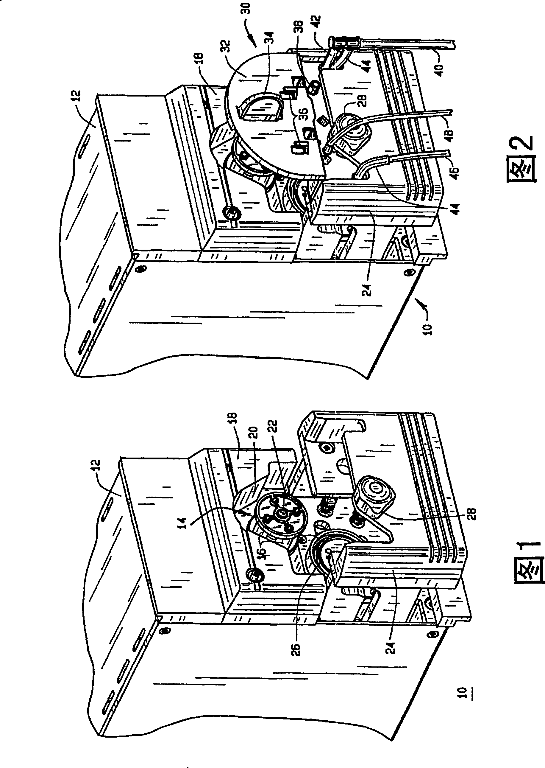
[0025] Figure 1 shows a partial perspective view of a peristaltic pump 10 for use in ophthalmic surgery according to the present invention. Housing 12 includes a pump head 14 having a plurality of rollers 16 retained within and extending from housing 12 . Backing plate 18 is attached to housing 12 and cooperates with pump head 14 to clamp a length of tubing between roller 16 and backing plate surface 20 . The pump head 14 moves relative to the housing 12 and backing plate 18 as described in detail below. In Figure 1, the pump head 14 is shown in an open position, ready for insertion of a pump barrel, as described below.

[0026] As will be described in further detail below, pump head 14 is preferably connected to a motor / motor (not shown), and pump head 14 rotates roller 16 about central axis 22 of pump head 14 such that roller 16 and backing plate 18 cooperate. Functions to compress or pinch a length of surgical tubing and peristaltically pump fluid from the surgical site t...


PUM


Abstract

A peristaltic pump (10) for use in ophthalmic surgery includes a housing (12), a pump head (14) having plurality of rollers (16), a backing plate (18) attached to the housing (12), and a length of surgical tubing (50). The rollers (16) and backing plate (18) cooperate to pinch the length of surgical tubing (50) to peristaltically pump fluids from a surgical site to a collection bag (64). At least one of the pump head (14) and the backing plate (18) is moveable, during operation of the pump (10), from a tubing pinched position to a tubing vent position. This movement allows the tubing (50) to be vented by removing the pinched closure of the tubing (50).

Description

technical field [0001] The present invention relates to depressurization of the suction path in a peristaltic pump after reaching an unacceptably high vacuum, and more particularly to gas decompression or air venting. Background technique [0002] During the use of peristaltic pumps, especially in ophthalmic surgery, occlusion of the suction path (including the surgical handpiece, suction tubing, pump barrel, and collection bag) can occur. Once a piece of tissue, such as a piece of cataract, blocks the suction port of a surgical handpiece, such as a phacoemulsification instrument, the vacuum within the suction path will begin to rise. If the occlusion is not cleared in time, the vacuum can become dangerous, i.e. after the occlusion is cleared, the excessive surge in the suction path will cause the eye to collapse and increase the intraocular pressure (IOP) of the eye sudden and sharp drop. This could cause serious damage to the eyes. [0003] Therefore, it is well known i...

Claims


Application Information

Patent Timeline
Patent Type & Authority Patents(China)
IPC IPC(8): F04B43/12F04B53/06
CPCF04B43/1261F04B53/06F04B43/1276F04B43/1284F05B2210/11Y10S417/00A61M1/92A61M1/80
Inventor 劳伦斯·J·卡尔詹姆斯·T·珀金斯罗伯特·弗里斯
Owner BAUSCH & LOMB INC
Features
  • R&D
  • Intellectual Property
  • Life Sciences
  • Materials
  • Tech Scout
  • Unparalleled Data Quality
  • Higher Quality Content
  • 60% Fewer Hallucinations
Learn More