
Electronic control device for IC engine

An electronic control device, a technology for an internal combustion engine, applied in electrical control, engine control, fuel injection control, etc., can solve problems such as internal combustion engine errors

Inactive Publication Date: 2008-12-03
MITSUBISHI ELECTRIC CORP
View PDF5 Cites 0 Cited by
  • Summary
  • Abstract
  • Description
  • Claims
  • Application Information

AI Technical Summary

Problems solved by technology

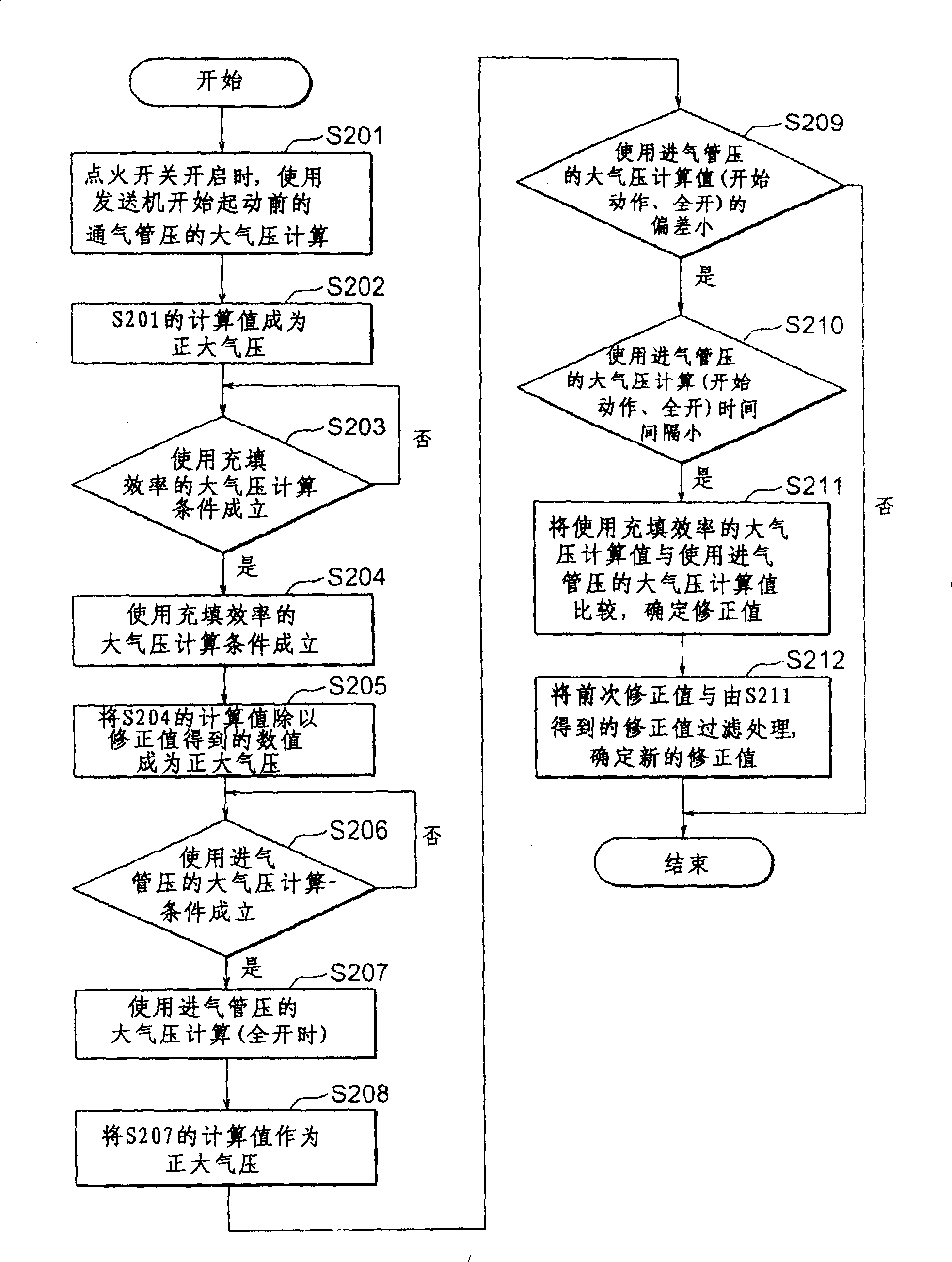
[0004] However, since the calculated value of the atmospheric pressure-related value including the atmospheric pressure using such charging efficiency information and the like is based on the charging efficiency or the correlation between the charging efficiency and The calculation formula determined by the ratio of the two-dimensional image value of the value to the actual measurement of the charging efficiency, errors may occur due to the individual differences of each internal combustion engine (the load due to the difference in the friction coefficient of the piston-cylinder (piston-cylinder), etc.)

Method used


Image

  • Electronic control device for IC engine
  • Electronic control device for IC engine
  • Electronic control device for IC engine

Examples


Embodiment 1

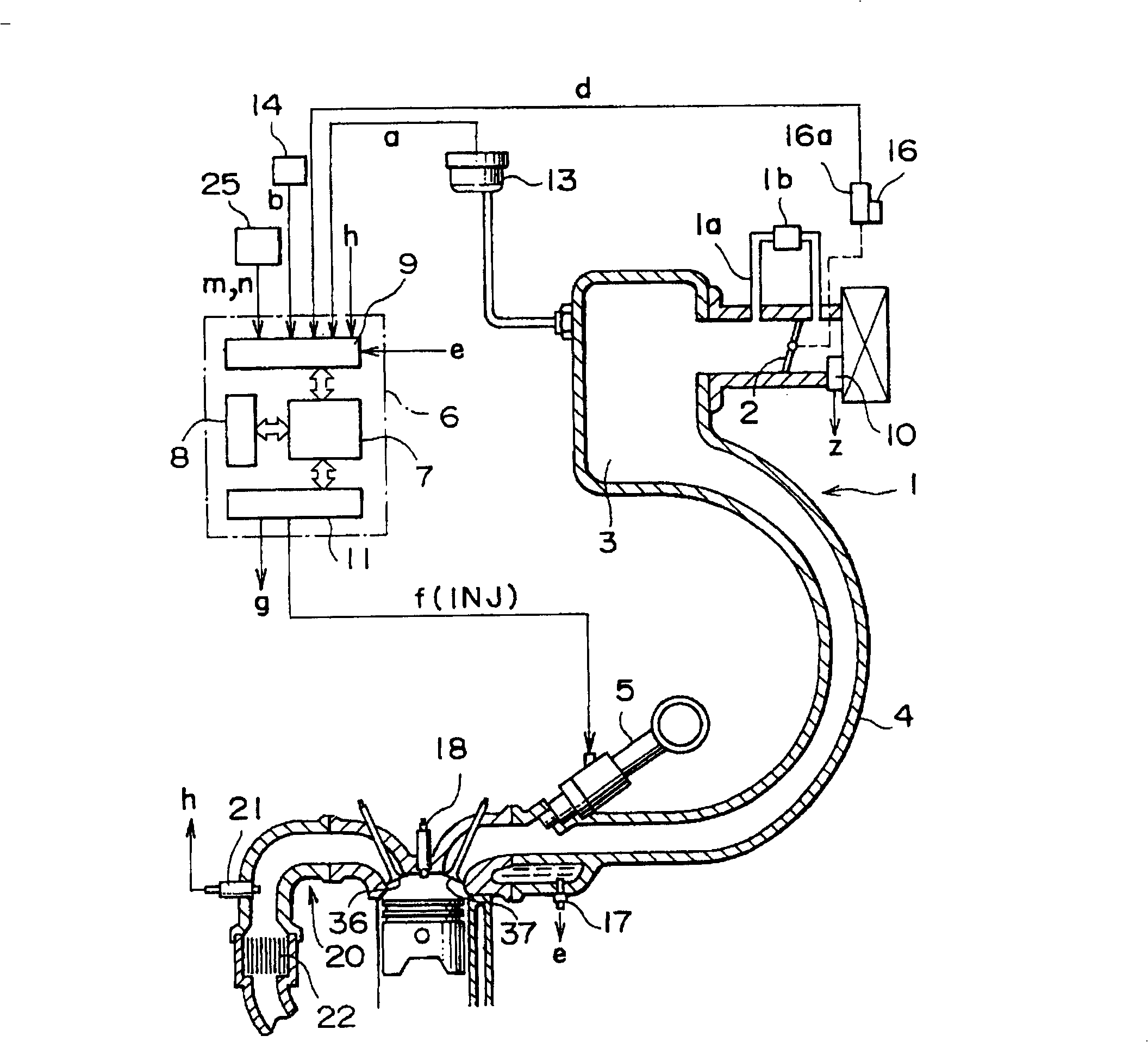
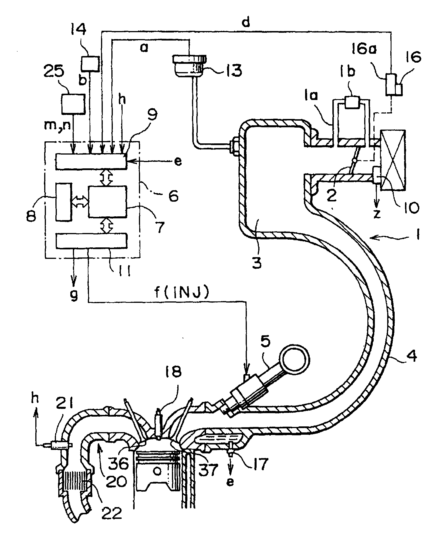
[0012] figure 1 It is a configuration diagram of an electronic control device for an internal combustion engine according to Embodiment 1 of the present invention.

[0013] In the figure, as an example, a 1-cylinder engine (engine) is briefly shown as a 4-cylinder engine for automobiles, and an intake system for measuring the amount of air passing through an air cleaner (air cleaner) is provided in the intake system 1 of the engine. The air flow sensor (air flow sensor) 10 of the air volume detection device is provided with a throttle valve (throttle valve) 2 linked with an accelerator pedal (not shown in the figure) to open and close on its downstream side. A surge tank (serge tank) 3 is provided on the side. Inhaled air enters the cylinder from the surge tank 3 through the intake valve 37 .

[0014] In this air intake system 1, there is provided a bypass passage 1a as a detour of the bypass throttle valve 2, and a flow control valve (hereinafter referred to as a bypass) fo...


PUM


Abstract

There are provided, various sensors for detecting the operating state of the internal combustion engine; a rotational speed sensor, an air flow sensor, a throttle sensor, an intake air pressure sensor of an internal combustion engine; a storage where the charging efficiency corresponding to the rotational speed and throttle travel in the standard atmospheric condition is previously stored and set as a two-dimensional map, for outputting the stored and set value corresponding to the rotational speed and the throttle travel; and a CPU correcting the atmospheric pressure relational value including the atmospheric pressure calculated based on information of the intake air amount, rotational speed, charging efficiency, and throttle travel of the internal combustion engine by using the atmospheric pressure relational value including the atmospheric pressure calculated based on information of the rotational speed, throttle travel, and intake tube pressure of the internal combustion engine.

Description

technical field [0001] The present invention relates to an electronic control device of an internal combustion engine which calculates and obtains an atmospheric pressure-related value including atmospheric pressure from other control parameters of the internal combustion engine, and uses it as an auxiliary parameter for control. Background technique [0002] Conventionally, for example, as shown in Japanese Patent Application Laid-Open No. 5-312087, an electronic control device for an internal combustion engine is known, which calculates an atmospheric pressure-related value including atmospheric pressure from information on the intake air amount, rotation speed, charging efficiency, and throttle valve opening of the internal combustion engine. . [0003] In addition, as shown in JP 2001-132522 A, for example, an electronic control device for an internal combustion engine is known that calculates an atmospheric pressure-related value including atmospheric pressure based on ...

Claims


Application Information

Patent Timeline
IPC IPC(8): F02D45/00F02D41/02F02D41/24F02D41/32G06G7/70
CPCF02D41/2451F02D2200/704F02D2200/0404F02D41/187F02D2200/0406F02D41/2441F02D41/32
Inventor 和田修一西本浩二松本纪生
Owner MITSUBISHI ELECTRIC CORP
Learn More