
Automation device for LED test table

A technology of light-emitting diodes and automation devices, which is applied to measurement devices, photometry, optical radiation measurement, etc., can solve the problems of easy tilt, complex structure, damage to light-emitting diodes, etc., and achieves the effect of simple structure and easy implementation.

Inactive Publication Date: 2008-12-24
杨少辰
View PDF5 Cites 0 Cited by
  • Summary
  • Abstract
  • Description
  • Claims
  • Application Information

AI Technical Summary

Problems solved by technology

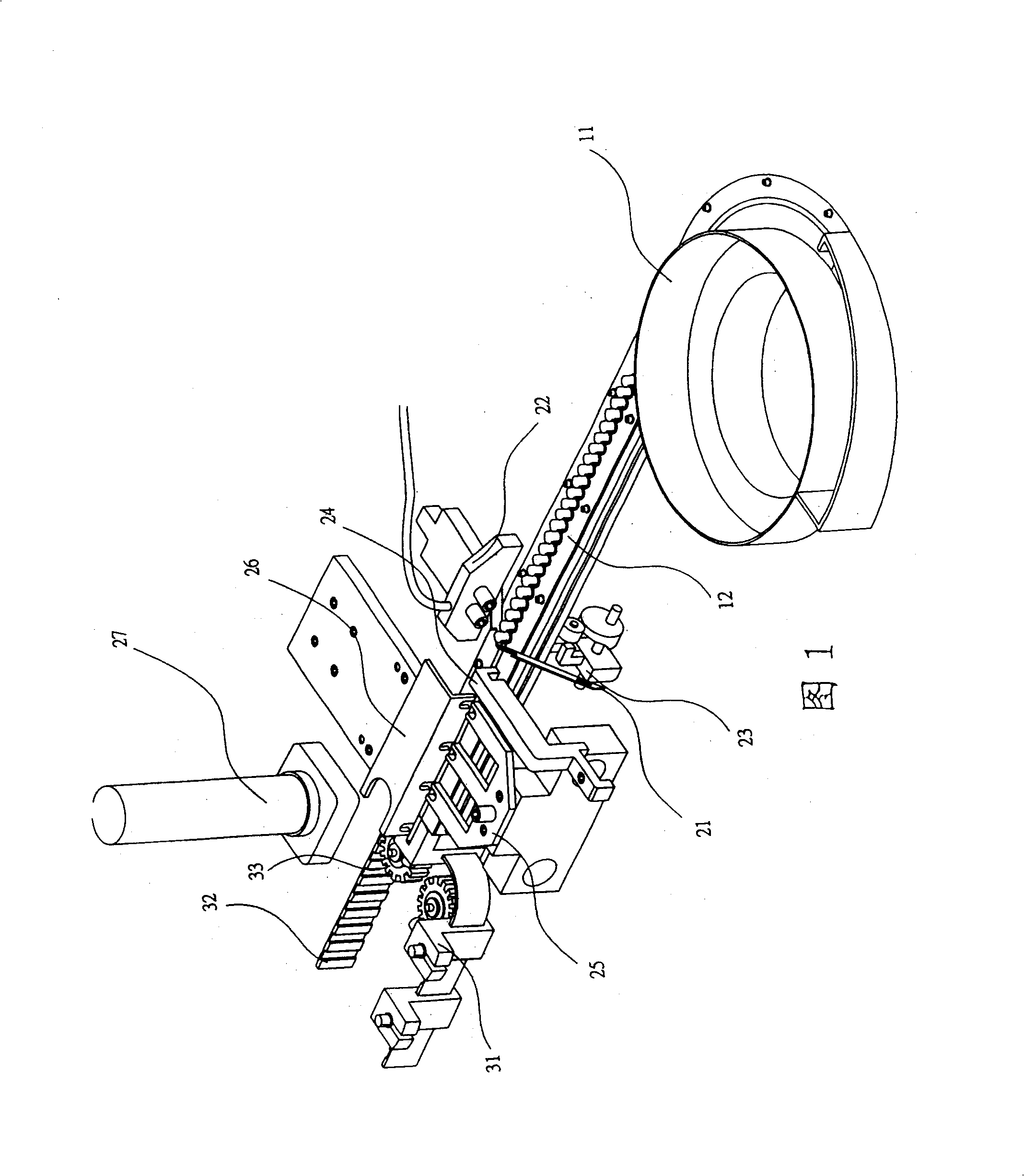
[0005] Since the action of the feeding jaw group is controlled by a cam, the longitudinal transmission wheel and the horizontal transmission wheel, and a guide claw is provided at the end of the blocking claw, when the feeding jaw group clamps the stitches of the light-emitting diodes, it will move from the blocking claw When it is sent to the position close to the guide claw, the feed auxiliary air supply port blows the light-emitting diode into the side blocking hole of the guide claw, the guide claw withdraws backward, and the light-emitting diode is positioned through the guide hole on the front face of the guide claw On the track, so as to realize the positioning of the light-emitting diodes in this way, the structure is complex, and the positioning is not accurate, and it is easy to tilt, which will easily cause damage to the light-emitting diodes when the belt claw group is held forward longitudinally.

Method used


Image

  • Automation device for LED test table
  • Automation device for LED test table
  • Automation device for LED test table

Examples


Embodiment Construction

[0032] The present invention will be further described in detail below in conjunction with the accompanying drawings and specific embodiments.

[0033] An automatic device for a light-emitting diode testing machine includes a group of feeding structures, a positioning testing structure and a group of discharging structures.

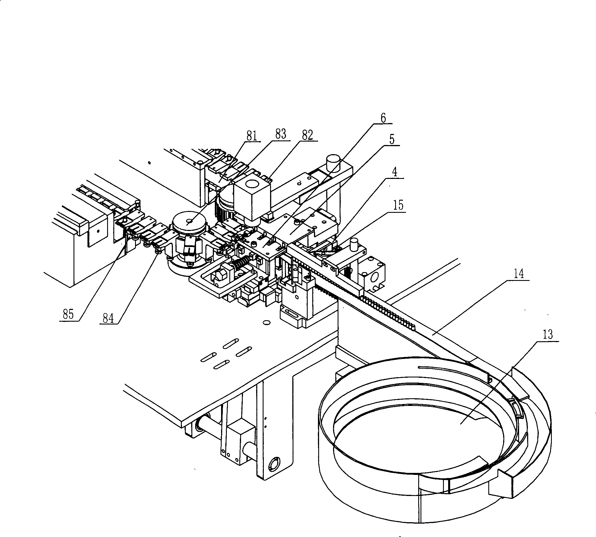
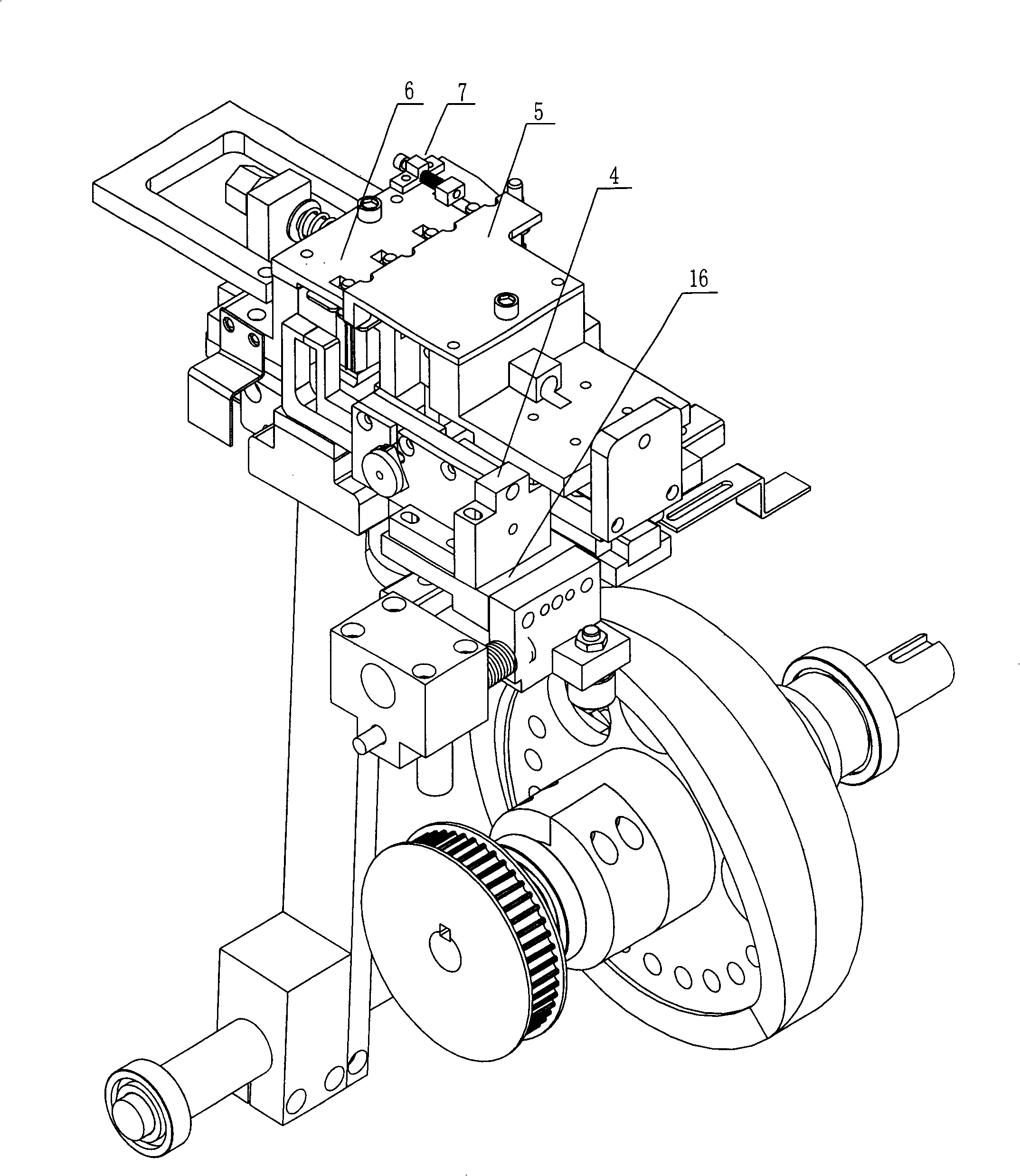
[0034] The feed structure is made up of the following components: See figure 2 , image 3, its feeding end is a circular vibrating plate 13, and a flat vibrating plate 14 is connected with it, and the flat vibrating plate 14 extends to the front end of the test section, and is just connected with the front end of the test section; the flat vibrating plate 14 is forward When extending to an appropriate place in front of the test section, a retaining claw 15 is arranged above; the feeding jaw group 4 is arranged on the large slide plate at the end side of the flat vibrating plate 14, and the feeding jaw set 4 is arranged on the small slide plate. There ar...


PUM


Abstract

The invention discloses an automatic device for a light-emitting diode testing machine, which consists of a feeding structure, a positioning testing structure and a discharging structure. The feeding structure includes a circular vibrating plate, a flat vibrating plate connected thereto, and a feeding jaw The positioning test structure includes the positioning claw group placed opposite the material claw group, and the first test group is placed directly below the positioning claw group. The discharge structure includes the transmission gear and the track matched with it. The feed jaws are clamped on the crawler belt, the feed jaw set is fixed on the large slide plate, and a pushing device is provided on the side of the small slide plate close to the feed jaw set, and the feed jaw set includes the feed jaw set , jaw base, baffle and swing device, the clamping jaw includes an upper jaw and a lower jaw, the upper jaw and the lower jaw are placed in the jaw base, the baffle is close to the other end of the jaw base, the upper A spring is arranged between the tail end of the jaw and the baffle plate, and a push block is arranged on the side of the upper jaw close to the push device, and the push block protrudes from the opening of the jaw seat, and the swing device and the jaw seat are movable The two pins pass through the elongated pin holes on the jaw seat and are fixedly connected with the upper jaw and the lower jaw respectively. The automatic device of the invention has simple structure and accurate positioning.

Description

technical field [0001] The invention relates to a light-emitting diode testing instrument, in particular to an automatic device for a light-emitting diode testing machine. Background technique [0002] After the LED is packaged, its luminance and light wavelength must be tested to ensure its yield or applicability, and the testing method must use a special LED testing instrument for detection. In recent years, there have been light-emitting diode testing instruments with a high degree of automation and reliable testing accuracy. [0003] The patent No. is 01274956.7, the authorized announcement number is CN 2519906Y, and the patent entitled "automatic device for light-emitting diode testing machine" has just announced a kind of such testing instrument. Please refer to Fig. 1, the patent is realized in this way: it is mainly composed of a group of feeding structure, a positioning test structure and a group of discharging structure, and the feeding structure is made up of the...

Claims


Application Information

Patent Timeline
Patent Type & Authority Patents(China)
IPC IPC(8): G01J1/02G01J9/00G01R31/26H01L21/66
Inventor 韩金龙罗会才杨少辰
Owner 杨少辰
Learn More