Gantry type numerical control cutting machine

A cutting machine, gantry type technology, applied in welding equipment, metal processing equipment, plasma welding equipment, etc., can solve the problems of bottom wear, affecting cutting accuracy, operation danger, etc., to ensure safety, improve moving effect, and avoid spark glare Effect

Active Publication Date: 2017-09-15
HEFEI FANGYUAN ELECTRICAL
View PDF5 Cites 0 Cited by
  • Summary
  • Abstract
  • Description
  • Claims
  • Application Information

AI Technical Summary

Problems solved by technology

[0003] The cutting machine is a relatively simple processing equipment, but most of the cutting machines in the prior art have a gantry structure, which will affect the cutting accuracy due to the large friction force driven by the gear when moving longitudinally. On the other hand, it will accelerate the wear of the bottom. It is very inconvenient. When operating the existing cutting machine, when the staff touches the moving machine with their limbs, they may be entangled or even injured. When operating the machine, they should not wear loose clothes or clothing with cords to prevent being entangled by the machine , In addition, when cutting, the operator must wear protective masks, welding gloves, hats, filter dust masks and soundproof earmuffs
It is strictly forbidden to directly observe the plasma arc without wearing protective glasses, and it is strictly forbidden to approach the plasma arc with exposed skin, otherwise the operation is very dangerous. Therefore, it is necessary to invent a gantry CNC cutting machine to solve the above problems

Method used


Image

  • Gantry type numerical control cutting machine
  • Gantry type numerical control cutting machine
  • Gantry type numerical control cutting machine

Examples


Embodiment Construction

[0020] The following will clearly and completely describe the technical solutions in the embodiments of the present invention with reference to the accompanying drawings in the embodiments of the present invention. Obviously, the described embodiments are only some, not all, embodiments of the present invention. Based on the embodiments of the present invention, all other embodiments obtained by persons of ordinary skill in the art without making creative efforts belong to the protection scope of the present invention.

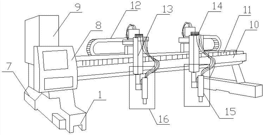
[0021] The present invention provides such as Figure 1-4 A kind of gantry type numerical control cutting machine shown, comprises main frame 1, and the bottom of described main frame 1 is provided with track 2, and described main frame 1 both sides bottom is fixedly provided with landing gear 3, and the inner side wall of described landing gear 3 is provided with There is a guide electromagnet 4, the bottom of the undercarriage 3 is provided with a lower magl...


PUM


Abstract

The invention discloses a gantry type numerical control cutting machine. A track is arranged at the bottom of a main rack; rising and falling frames are fixedly arranged at the bottoms of the two sides of the main rack; guiding electromagnets are arranged on the inner side walls of the rising and falling frames; lower magnetic levitation electromagnets are arranged at the bottoms of the rising and falling frames; upper magnetic levitation electromagnets are arranged on the tops of the lower magnetic levitation electromagnets, and are arranged at the bottom of the track; a pressure reducer is arranged on one side of the main rack; a numerical control system is arranged on the top of the main rack; a power source control cabinet is arranged on one side of the numerical control system; and a steel belt transmission device is arranged on one side of the power source control cabinet. According to the gantry type numerical control cutting machine, a power-on coil is controlled to be powered on through the power source control cabinet, the magnetic levitation movement effect is achieved, the movement effect can be improved easily; and by arranging a protective cover, it is easily avoided that a worker is scalded because of high temperature during cutting, and dazzling caused by sparks is avoided; and by arranging an infrared sensor, the safety of the worker can be guaranteed easily.

Description

technical field [0001] The invention relates to the field of cutting machine equipment, in particular to a gantry type numerical control cutting machine. Background technique [0002] As we all know, this type of cutting machine is a gantry structure, with a horizontal span of 3m, 4m, 5m, 6m, 8m and other specifications, all of which are driven by two sides, with stable operation, good configuration, and high work efficiency. It can be used for various carbon steel, Large, medium and small steel plates made of manganese steel, stainless steel and other metal materials. It can also be configured with multiple cutting torches according to user requirements, or configured as a dual-purpose cutting method for special-shaped cutting and straight cutting, and an optional capacitor or plasma automatic height adjustment system. [0003] The cutting machine is a relatively simple processing equipment, but most of the cutting machines in the prior art have a gantry structure, which w...

Claims


Application Information

Patent Timeline
Patent Type & Authority Applications(China)
IPC IPC(8): B23K10/00
CPCB23K10/00
Inventor 许亮张舰赵云龙
Owner HEFEI FANGYUAN ELECTRICAL
Why Eureka
Try Eureka