Supercharge Your Innovation With Domain-Expert AI Agents!

Laser oscillator

A laser oscillator and laser technology, applied in the direction of lasers, laser components, phonon exciters, etc., can solve the problems of zero output and laser difficulties

Inactive Publication Date: 2008-12-24
FANUC LTD
View PDF6 Cites 0 Cited by
  • Summary
  • Abstract
  • Description
  • Claims
  • Application Information

AI Technical Summary

Problems solved by technology

However, although there is a possibility that the output becomes completely zero in the case of using a back-up electrode, it is still difficult to control the laser light stably at a low output.

Method used


Image

  • Laser oscillator
  • Laser oscillator
  • Laser oscillator

Examples


Embodiment Construction

[0054] Hereinafter, embodiments of the present invention will be described with reference to the drawings. In the following drawings, the same reference numerals are assigned to the same parts. These images have been scaled appropriately for ease of understanding.

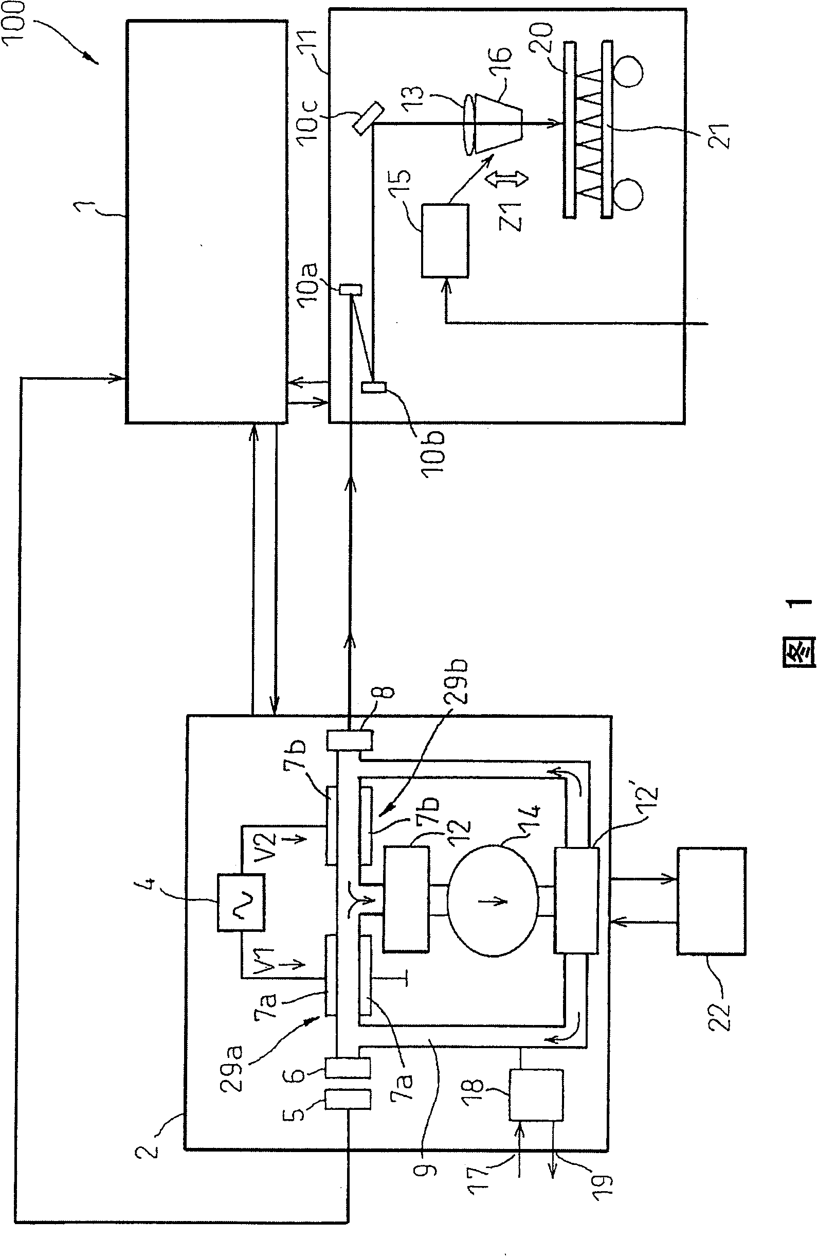
[0055] FIG. 1 is a schematic diagram of a laser device having a laser oscillator 2 according to the present invention. The laser device 100 is mainly used for metal processing and includes a laser oscillator 2 and a laser processing machine 11 . As shown in FIG. 1 , these laser oscillators 2 and laser processing machines 11 are electrically connected to each other through a control device 1 .

[0056] The laser oscillator 2 is a high-output oscillator of a discharge excitation type, for example, a carbon dioxide gas (carbon gas) laser that outputs 1 KW or more. The laser oscillator 2 has a discharge tube 9 connected to a laser gas pressure control system 18 . Laser gas pressure control system 18 can supply lase...


PUM


Abstract

A laser oscillator (2) is provided, which has: a first electrode pair (7a); a second electrode pair (7b); a discharge power supply ( 4); and at least one of the following units: during the pulse discharge of the discharge power supply (4), for the first discharge phase (X1) in the first electrode pair (7a) and the second electrode pair (7b) The discharge phase control unit (53) that controls the second discharge phase (X2) is different from each other; during pulse discharge, in order to make the first duty ratio (Y1) in the first electrode pair (7a) and the second electrode A duty ratio control unit (53) that controls the second duty ratio (Y2) in (7b) to be different from each other; and during pulse discharge, to make the first pulse in the first electrode pair (7a) A pulse frequency control unit (53) for controlling the frequency (Z1) and the second pulse frequency (Z2) in the second electrode pair (7b) to be different from each other. Thus, the laser output can be quickly controlled while stabilizing the discharge in the discharge electrode.

Description

technical field [0001] The present invention relates to a laser oscillator that excites gas or solid medium to obtain laser output. Background technique [0002] Generally, the laser output from the laser oscillator is controlled by correspondingly increasing or decreasing the output of the power supply for laser oscillation. That is, in a general laser oscillator, when an increase in laser output is requested, the power output is increased, and when a reduction in laser output is requested, the power output is decreased. [0003] For example, a laser oscillator disclosed in JP-A-7-122799 has a plurality of electrode pairs and a plurality of power supply units respectively corresponding to the electrode pairs, and quantitatively controls laser output by individually controlling these power supply units. [0004] Figure 9 It is a graph showing the relationship between the laser output and the like of the conventional laser oscillator disclosed in JP-A-7-122799 and time. Su...

Claims


Application Information

Patent Timeline
Patent Type & Authority Patents(China)
IPC IPC(8): H01S3/06H01S3/032H01S3/10
CPCH01S3/036H01S3/073H01S3/09702H01S3/0971H01S3/10038H01S3/104
Inventor 江川明安藤稔小林英二渡边武
Owner FANUC LTD
Features
  • R&D
  • Intellectual Property
  • Life Sciences
  • Materials
  • Tech Scout
  • Unparalleled Data Quality
  • Higher Quality Content
  • 60% Fewer Hallucinations
Learn More