Electric energy storage type stapling machine

A stapler and energy storage technology, which is applied in the direction of binding, can solve the problems of difficult processing size, increased stapler size, increased output load, etc., and achieves low power requirements, good staple effect, and prevents burning. bad effect

Inactive Publication Date: 2009-01-14
廖金志
View PDF7 Cites 2 Cited by
  • Summary
  • Abstract
  • Description
  • Claims
  • Application Information

AI Technical Summary

Problems solved by technology

Due to the whole process from the output power of the motor to the final driving of the staple sheet to press the needle down out of the needle slot, the force is a rigid transmission process, which has the following technical disadvantages: 1) due to the limitation of the motor, structure and cost, generally Electric staplers can only staple 2 to 20 sheets of paper. Under the current deceleration and force-increasing conditions, in order to increase the number of staples, a motor with a larger power and size is required, which will increase the size of the stapler.
2) The needle force is continuously acting on the needle during half of the needle cycle. When the needle is soft and the needle is blunt, the effect of the needle becomes poor, and the needle may not penetrate the paper, and the needle may be caught in the paper. Faults in the book needle slot, etc.
3) When the book needle is clamped in the book needle groove, the staple piece can no longer move down, nor can it return to the initial state, but because a staple cycle is not completed, the circuit breaker will not be disconnected, and the motor will continue to work and will Increasing the output load often leads to burning out the motor
4) Moreover, due to the limitation of the gear set and the box structure, once the needle is clamped, it is generally difficult for the electric stapler to pop out the needle slot and take out the clamped needle
However, the elastic sleeve of this type of model must be made of special memory elastic material, which has defects such as high material cost, difficult control of processing size, and high production cost.

Method used


Image

  • Electric energy storage type stapling machine
  • Electric energy storage type stapling machine
  • Electric energy storage type stapling machine

Examples


Embodiment 1

[0041] FIG. 9 is a three-dimensional schematic view of the disassembled structure of Embodiment 1 of the present invention. Embodiment 1 of the energy storage type stapler of the present invention includes a box 100 with a staple holder 101, the box 100 includes a left box and a right box that can be docked and assembled; Straight or curved ribs and compartments for assembling parts are formed on the top, including a battery compartment 130 and an external power socket 131; the box 100 includes a supporting base 120;

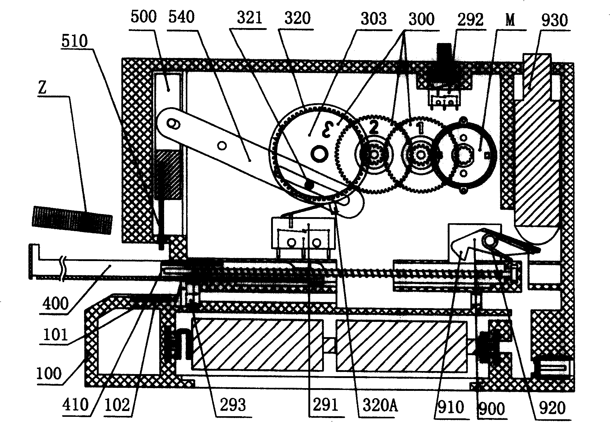
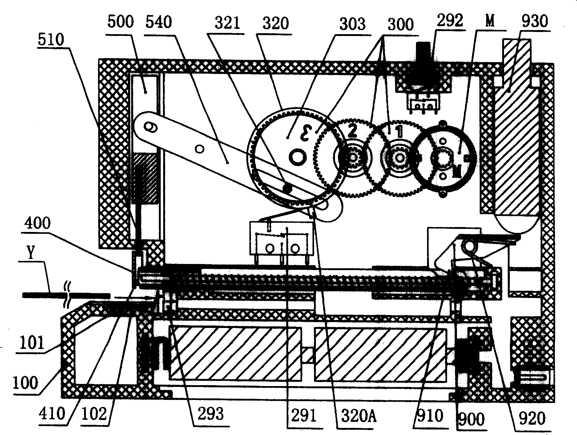
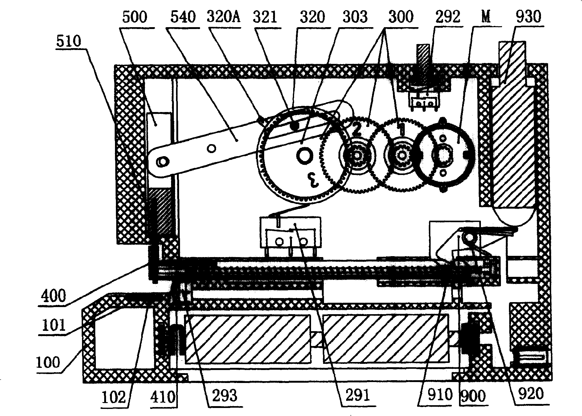
[0042] Inside the box 100, a control switch 200 and its circuit, a motor M, a gear set 300 for deceleration and boosting, and a running wheel 320 are installed. In the case 100 , a staple slot 400 and a stapler 500 are vertically slidably fitted with each other, and the stapler 500 and the base 120 are vertically installed in the case 100 . In the book needle groove 400, an elastic needle pusher 410 is slidably fitted, and the stapler 500 is equipped with a sta...

Embodiment 2

[0059] like Figure 17-19 , which are the cross-sectional schematic diagrams of the assembly structure at three moments during the operation process of the embodiment 2 of the present invention, namely, when the needle is unloaded from the slot, the paper is fed and ready to be sent, and the sheet is released and lifted. Embodiment 2 of the energy storage type stapler of the present invention, except that the following elastic energy storage device 600 and related structures are different from Embodiment 1, the rest of the structures are the same as Embodiment 1:

[0060] The energy storage member includes a torsion spring 610 and an auxiliary lever 614 hinged on respective support shafts 620A, 620B, the outer end of the torsion spring 610 is hooked to the stapler 500, and its middle is hinged by the support shaft 620A Between the two inner sidewalls of the box 100 , the two ends of the auxiliary lever 614 are respectively hinged on the inner end of the torsion spring 610 and ...

Embodiment 3

[0065] like Figure 20-25 , shows the cross-sectional schematic diagram of the assembly structure of the embodiment 3 of the present invention at six moments during the operation process of loading the needle out of the groove, starting the paper feeding, storing the energy for firing, releasing the energy for pressing the needle, lifting the button, and lifting the piece for braking.

[0066] Embodiment 3 of the energy storage type stapler of the present invention, except that the following elastic energy storage device 600 and related structures are different from Embodiment 1, the rest of the structures are the same as Embodiment 1:

[0067] The energy storage part is a leaf spring 615, the outer end of the leaf spring 615 hooks the nailer 500, the middle part is hinged between the two inner walls of the box 100 through the upper and lower support shafts 621, 622, and its The inner end is bounded in a bounding frame 630 hinged on said eccentric shaft.

[0068] like Figur...


PUM


Abstract

The invention relates to an electric energy storage stapling machine, comprising a box which contains a control switch and a circuit, a motor, a gear group for reducing speed and increasing force, and a wheel. The last wheel of the gear group is concentric with the wheel and connected via an eccentric axle, the box contains sliding engaged staple groove and stapling device with some angle, the box contains a flexible energy storage device, a locking releaser for locking and releasing the stapling machine, the middle of the flexible energy storage device is hinged between two inner side walls of the box while its outer end is hooked on the stapling machine and inner end is directly or indirectly hinged on the eccentric axle, the circumference of the wheel is disposed with a dial block for dialing block and locking block and a dial rod for dialing the control switch. The invention has low demand on motor power, and low cost, which it can avoid destroying motor in clamped condition.

Description

technical field [0001] The present invention relates to an office stationery, more specifically, the present invention relates to an electric stapler. Background technique [0002] All staplers have to go through the cycle process of pressing the staples downward and then rising back to the highest position. During this process, the staples may be caught in the staple slots and difficult to remove, resulting in the staple sheet not being able to return. The failure of the initial position, especially for electric staplers, the stapler is installed in the stapler. Once the stapler is stuck or the needle is clamped, the entire stapler will be linked and difficult to recover and raised to the highest level. Position; the existing electric stapler, when the needle is clamped in the needle groove, according to the way the stapler returns to the initial position and the structure is different, it can be divided into motor reverse type electric stapler and Mechanically controlled ...

Claims


Application Information

Patent Timeline
Patent Type & Authority Patents(China)
IPC IPC(8): B42B4/00
Inventor 廖金志
Owner 廖金志
Why Eureka
Try Eureka