
Canopy leaf chamber for determining plant canopy population photosynthesis

A photosynthesis and photosynthesis chamber technology, which is applied in the field of biological research instruments, can solve the problems of photosynthesis measurement error, unreliable sealing, and poor light transmittance.

Inactive Publication Date: 2009-01-14
SHANGHAI JIAO TONG UNIV
View PDF6 Cites 2 Cited by
  • Summary
  • Abstract
  • Description
  • Claims
  • Application Information

AI Technical Summary

Problems solved by technology

[0006] 1. The sealing of the canopy leaf chamber is poor, especially there is inevitably a gap between the opening base of the canopy leaf chamber and the lawn plant (CPY-2) or the edge of the pot (CPY-3). For other plastic wraps, the gas in the canopy leaf chamber will always exchange with the outside world through the gap. This unreliable sealing will bring great errors to the measurement of canopy photosynthesis;
[0007] 2. Due to the unavoidable contact with sediment during the measurement of canopy photosynthesis, after several measurements, the polyethylene material in the canopy chamber will be worn out, and the light transmission will become poor, thus affecting the light intensity in the canopy chamber and light quality, resulting in errors in the measurement of photosynthesis, resulting in the inability to compare the measured values ​​of different batches at the same level
[0008] 3. Air flow in and out is easily affected
The air path inlet and outlet of CPY-2 and CPY-3 are designed at the base of the canopy leaf chamber, located below the photosynthetic organs such as leaves and stems of plants during the measurement. The blockage of leaves, on the other hand is severely disturbed by the poor sealing of the base of the canopy leaf chamber

Method used


Image

  • Canopy leaf chamber for determining plant canopy population photosynthesis

Examples


Embodiment Construction

[0017] The technical solution of the present invention will be further described below in conjunction with the accompanying drawings.

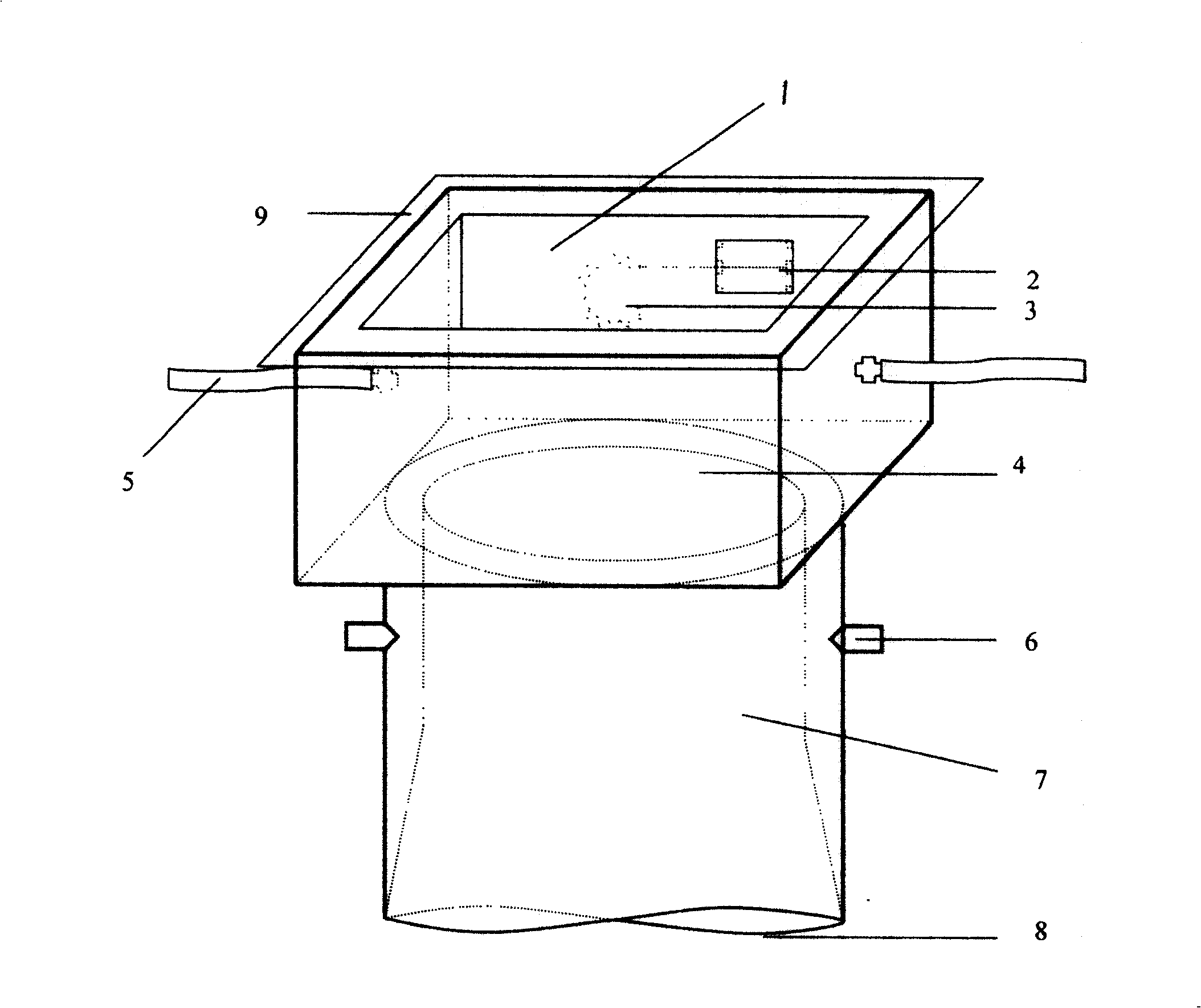
[0018] Canopy leaf chamber structure of the present invention such as figure 1 As shown, it consists of a square photosynthetic chamber 1 and a cylindrical soil fixture 7. The surrounding side walls and the bottom wall of the photosynthetic chamber 1 are made of transparent plexiglass to ensure the light transmission of the canopy leaf chamber. A small-sized fan 3 is installed in the side wall of photosynthetic chamber 1 (can adopt the small fan for CPU heat dissipation on home computer), and fan 3 is controlled by 2 joints of No. 5 batteries and switch 2 installed outside the side wall, photosynthetic chamber The top wall of 1 is sealed with double-sided adhesive tape and photosynthetic film 9, and the photosynthetic film can be replaced frequently to ensure the good light transmission of the photosynthetic chamber 1. A plastic hose 5 is res...


PUM

PropertyMeasurementUnit
diameteraaaaaaaaaa
diameteraaaaaaaaaa

Abstract

Present invention relates to a canopy leaf chamber for determining plant canopy colony photosynthetic activity. It contains quadratic photosynthetic chamber and columned soil fixing body, wherein soil fixing body of canopy leaf chamber bottom set with knob basal portion being corrugation notch, capable of easy inserting amboceptor in soil to form inclosed canopy leaf chamber, amboceptor upper port inosculation with photosynthetic chamber lower wall round opening to make canopy leaf chamber intracavity forming one integral, photosynthetic chamber upper wall sealed by two side glue and photosynthetic film to ensure photosynthetic chamber steady light permeability, photosynthetic chamber sidewall installed one small size fan controlled by external battery and switch, fan capable of rapid making canopy leaf chamber gaseous reaching equalization. Plastic hose respectively is installed on two opposite sidewall centre of Photosynthetic chamber connected with photosynthetic activity calcimetre sample room gas path. Said invention can combine with photosynthetic activity calcimetre for determining different kinds of plantal colony, breath and transpiration.

Description

technical field [0001] The invention relates to a canopy leaf chamber for measuring the photosynthesis of plant canopy groups, which is connected to the air path of the sample chamber of a photosynthesis measuring instrument, according to the CO in the canopy leaf chamber 2 , O 2 、H 2 The reference change of O is used to measure the group photosynthesis, respiration and transpiration of canopy leaf indoor plants, which belongs to the field of biological research instruments. Background technique [0002] Photosynthesis is a process in which plants use light energy to synthesize inorganic substances such as carbon dioxide and water into organic substances that can be used by humans and release oxygen. Almost all human food comes directly or indirectly from photosynthesis. The study of plant photosynthesis has always been the focus of life science research. [0003] The photosynthesis measuring instrument is one of the most widely used instruments for studying photosynthesi...

Claims


Application Information

Patent Timeline
Patent Type & Authority Patents(China)
IPC IPC(8): G01N33/00
Inventor 王兆龙朱燕华刘一明李洁
Owner SHANGHAI JIAO TONG UNIV
Learn More