
Steel rail wear laser visual dynamic measuring method

A technology for dynamic measurement and rail wear, applied in the field of measurement, can solve the problems that the measurement sensor cannot have large vibration, affect the accuracy and reliability of the measurement result, and the conversion link is not well solved, and achieves low cost and speed. The effect of fast and reducing equipment cost

Inactive Publication Date: 2009-02-18
BEIHANG UNIV
View PDF2 Cites 5 Cited by
  • Summary
  • Abstract
  • Description
  • Claims
  • Application Information

AI Technical Summary

Problems solved by technology

The disadvantage of this method is that the upper edge and left edge of the image are used as the positioning reference, so the measurement sensor is required not to have large vibrations, so it is more suitable for static measurement
In fact, the measurement sensor installed on the locomotive must have a large vibration, which affects the accuracy and reliability of the measurement results
In addition, in foreign countries, two sets of measuring sensors are used to measure both sides of the same rail, and the measurement results of the side without wear are used as the reference. Although this method solves the impact of vibration on the measurement results, it is costly and requires two sets of measuring sensors. Unification of systems, complex operation
At present, the rail wear detection system researched in China is basically similar to that abroad, and because the conversion link from the measurement coordinate system to the standard (design) coordinate system has not been solved well, the actual research device is only used for static experimental research, and there is no Can solve the automatic measurement of rail wear under dynamic conditions

Method used

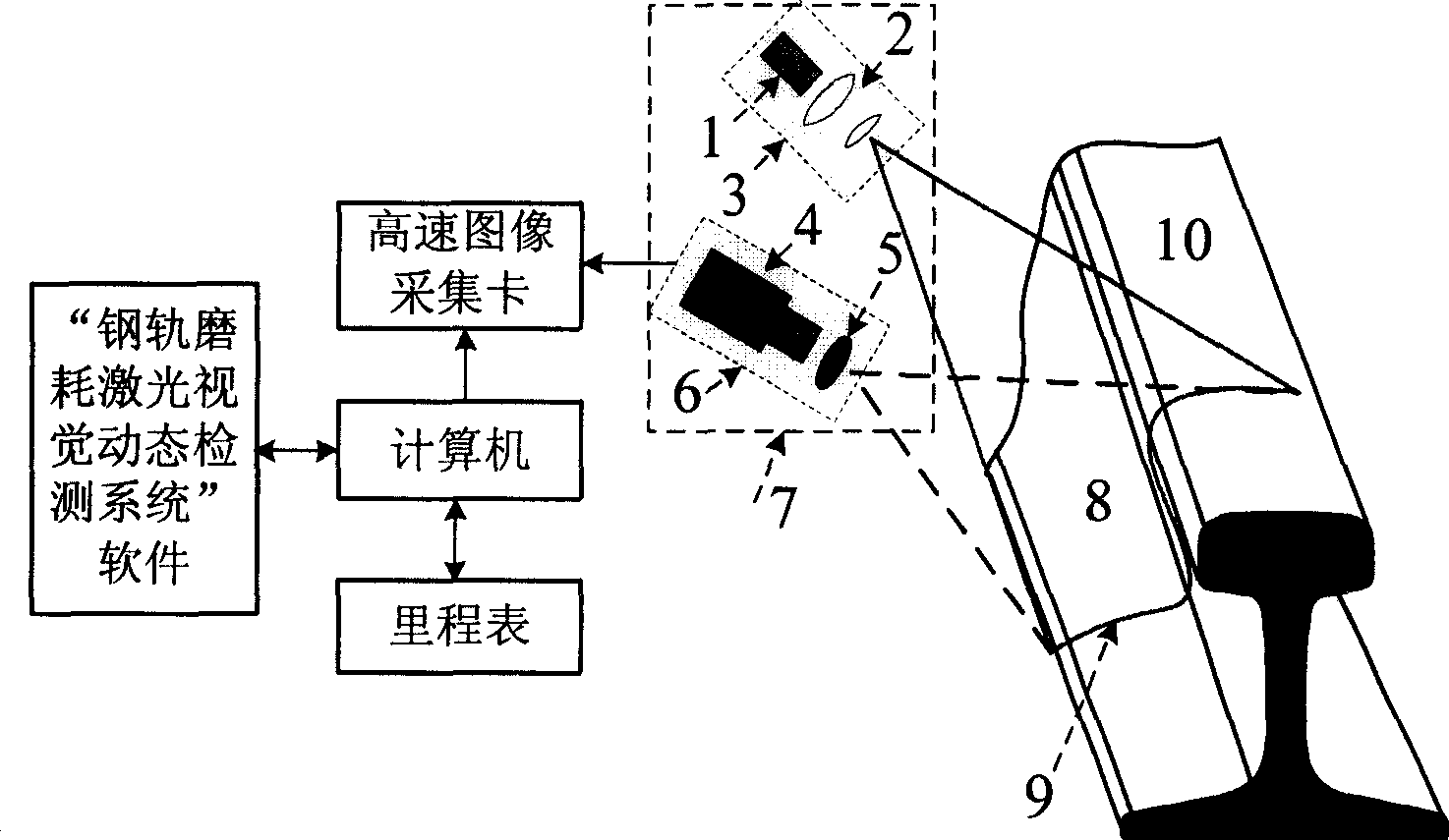
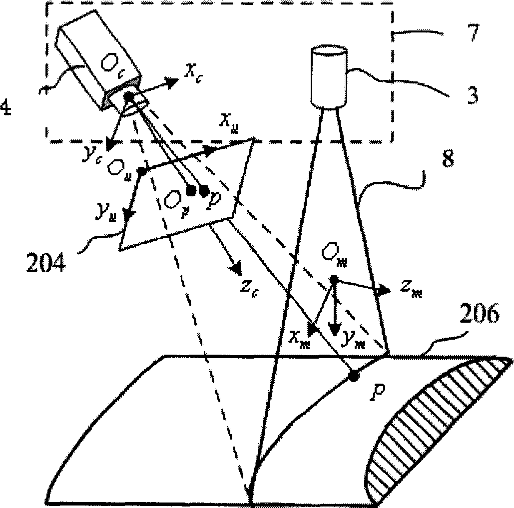
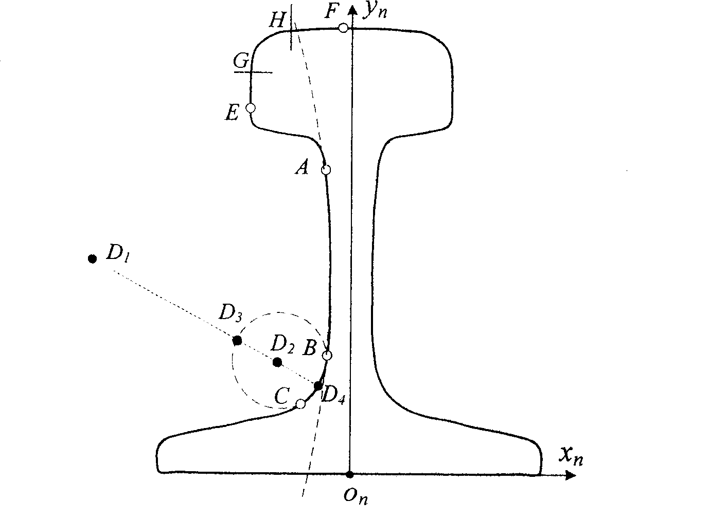

Image

  • Steel rail wear laser visual dynamic measuring method
  • Steel rail wear laser visual dynamic measuring method
  • Steel rail wear laser visual dynamic measuring method

Examples


Embodiment

[0096] Propose measuring device and measuring method according to the present invention, design actual laser vision sensor, carry out on-the-spot dynamic measurement to rail, the software interface of measuring system is as follows Figure 6 shown.

[0097] Figure 7 A measured image including a 50kg rail and the extracted contour feature image are given. Figure 8 is the profile of the rail section in the survey coordinate system and the profile transformed to the design coordinate system; Figure 9 After alignment, measure the profile and design the profile.

[0098]The final measured wear is: vertical wear is 1.9mm, side wear is -0.1mm, total wear is 1.8mm, and the rail type is 50R (50kg right rail). On the PIV3.0 computer, the single measurement time is 25.5ms.

[0099] Figure 10 When the train stops, the same fixed rail surface is measured continuously for 540 times, and the rail surface wear repeatability error curve is obtained. The RMS errors are: 0.10mm, 0.04mm...


PUM


Abstract

The disclosed measuring device is composed of laser vision sensor, computer, image acquisition card in high speed, calibrating target drone and measuring software. The method includes steps: after imaging system for rail section images light plane projected from laser projector, the image acquisition card captures rail section images and sands them to computer. Processing the collected images, the computer picks up image coordinates of sectional feature contour, as well as calculates out vertical abrasion, side abrasion and total abrasion based on measured model. The invention is capable of measuring sectional contour of rail in single side, vertical abrasion, side abrasion and parameter of total abrasion through single laser vision sensor.

Description

technical field [0001] The invention belongs to the technical field of measurement and relates to a non-contact dynamic measurement method for comprehensive parameters of rail wear. Background technique [0002] The condition of railways is closely related to safety, especially for high-speed trains. Regular inspection of rails is very important to plan properly and keep maintenance costs low. Early measurement of rail wear and deformation can help to develop a better maintenance schedule to avoid emergency treatment when dangerous conditions are observed. On the other hand, early maintenance can make better use of limited manpower and equipment resources. utilization, thereby reducing costs. In addition, proper maintenance reduces noise pollution caused by poor contact between wheels and rails. In recent years, my country's railway speed-up and heavy-duty transportation have been vigorously developed, and passenger and freight volumes and traffic density have increased s...

Claims


Application Information

Patent Timeline
Patent Type & Authority Patents(China)
IPC IPC(8): G01B21/20G01B21/04G01B11/24G01B11/03B61K9/08B61K9/00
Inventor 周富强张广军朱奎义闫伟江洁魏振忠
Owner BEIHANG UNIV
Learn More