High resolution ratio micro optical device parallel direct-writing producing method

A manufacturing method and high-resolution technology, which can be used in optical components, semiconductor/solid-state device manufacturing, optics, etc., and can solve the problems of complex manufacturing process, not widely used, and low resolution.

Inactive Publication Date: 2009-03-18
NAT UNIV OF DEFENSE TECH
View PDF5 Cites 0 Cited by
  • Summary
  • Abstract
  • Description
  • Claims
  • Application Information

AI Technical Summary

Problems solved by technology

Furthermore, the typical value of the scanning line spacing is about 1 μm, and the writing speed is usually about 10 mm / s. It takes 1 to 2 hours to complete the exposure of a 10 mm wafer, and the writing speed is very slow.
In addition, although the excimer laser ablation method, laser deposition and etching method can be classified into the laser direct writing series, the resolution of the former is low when making optical devices, and the manufacturing process of the latter is complicated and the cost is high. widely used

Method used


Image

  • High resolution ratio micro optical device parallel direct-writing producing method
  • High resolution ratio micro optical device parallel direct-writing producing method
  • High resolution ratio micro optical device parallel direct-writing producing method

Examples


Embodiment 1

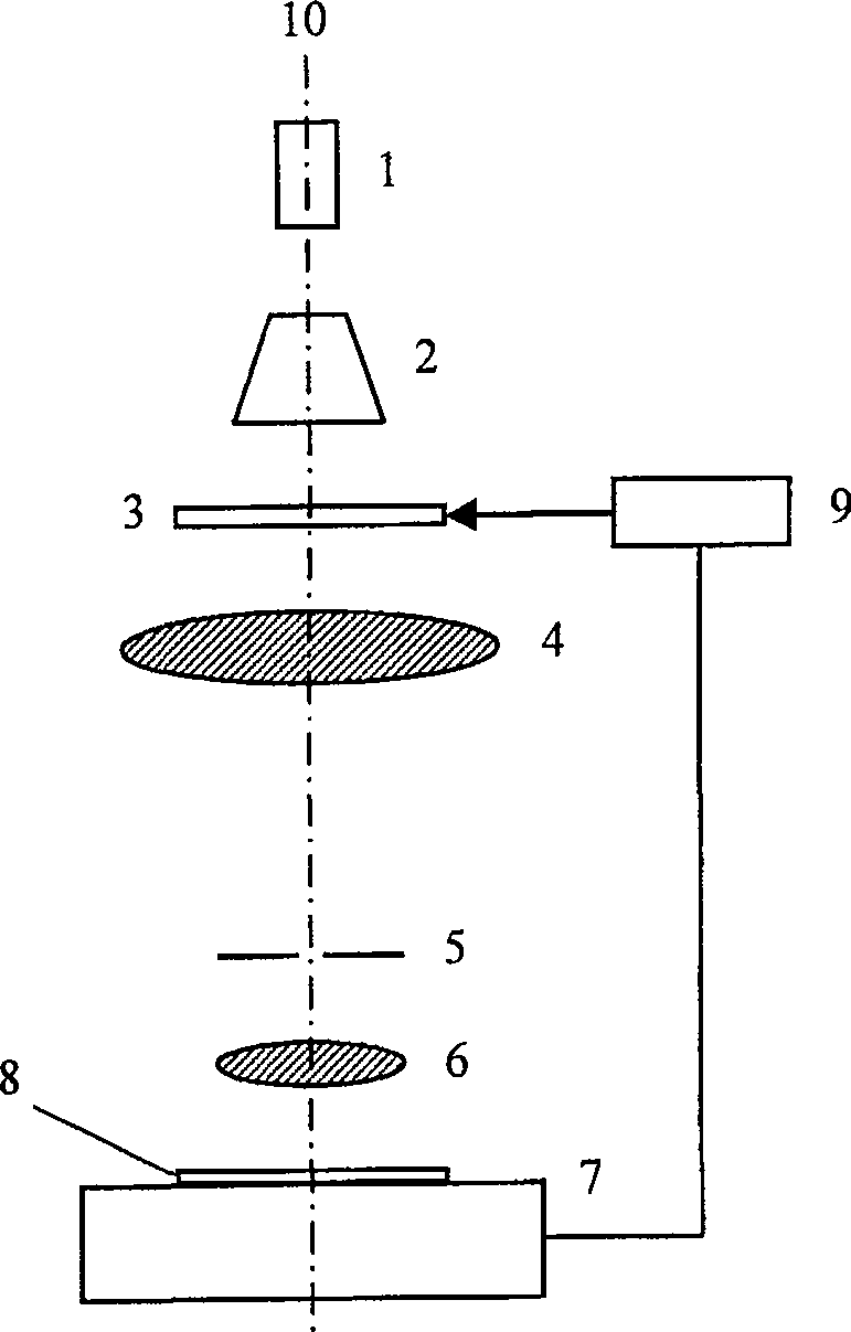
[0051] like figure 1 As shown, the micro-optical device parallel direct writing production system includes a light source 1, a beam expander collimator 2, a transmission type electrical addressing spatial light modulator 3, and a Fourier transform lens arranged in sequence on the optical axis 10 in the following order 4. Spatial filter 5, objective lens 6 and two-dimensional precision displacement platform 7. Also include the computer 9 that is provided with graphics generation software in the machine, the spatial filter 5 is placed on the rear focal plane of the Fourier transform lens 4, the spatial light modulator 3 is connected with the display video expansion output port of the computer 9 by wires, and Controlled by computer 9 and input graphics signal. The light source 1 is an ultraviolet light source, and may also be a He-Cd laser. The two-dimensional precision displacement platform 7 is connected with the computer 9, and the two-dimensional precision displacement plat...

Embodiment 2

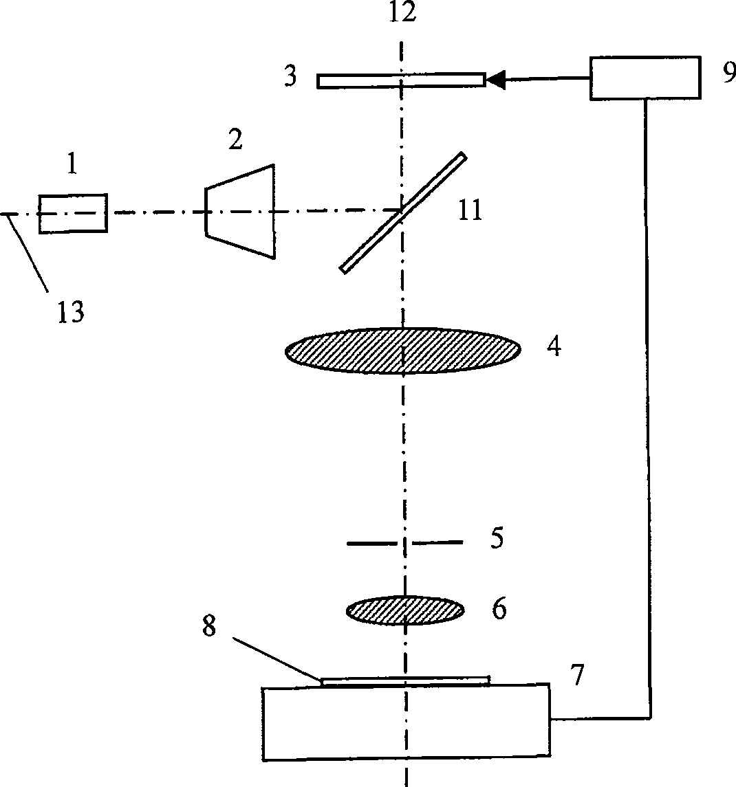
[0063] like figure 2 As shown, the micro-optical device parallel direct writing production system includes reflective electrical addressing spatial light modulator 3, beam splitter 11, Fourier transform lens 4, The spatial filter 5, the objective lens 6 and the two-dimensional precision displacement platform 7 also include the light source 1 and the beam expander collimator 2 on the second optical axis 13, and also include a computer 9 provided with graphics generation software in the machine, the first The optical axis 12 and the second optical axis 13 intersect perpendicularly at the beam splitter 11, the angle between the normal of the beam splitter 11 and the two optical axes is 45°, and the spatial filter 5 is placed in the Fourier transform lens 4 On the rear focal plane, the spatial light modulator 3 is connected to the display video expansion output port of the computer 9 through wires, and is controlled by the computer 9 and input graphic signals. The light source 1...


PUM


Abstract

The invention discloses a high resolution micro optical device parallel direct write making method and system, adopting electric addressing spatial light modulator, implements light intensity modulation by computer control and adopts time fractionizing method to expand dynamic range of exposure, and implement light intensity modulation fractionization and obtains high resolution photoetching exposure of exposure dosage and spatial positions; it adopts a high reduction power optical system based on combination of Fourier transform lens and objective to make the smallest characteristic size of the made micro optical device reach micron and submicron levels. And it uses the pattern splicing technique to make large-sized micro optical devices. And it has inherent parallel characteristic by adopting a method of making surface exposure on patterns one by one, largely increasing making rate and accuracy of micro optical devices and reducing production cost and the device structure is simple and reliable.

Description

technical field [0001] The invention relates to the field of manufacturing micro-optical devices, in particular to a high-resolution parallel direct-writing manufacturing method for micro-optical devices. Background technique [0002] Laser direct writing technology was proposed in the mid-1980s with the development of large-scale integrated circuits. Although the history is not very long, it has made great progress. In the early 1990s, the laser direct writing system began to be widely used in the production of micro-optical devices, which greatly improved the performance of micro-optical devices and laid a good foundation for the promotion and application of micro-optical technology. [0003] Most of the existing relatively mature laser direct writing systems are point-by-point exposure, and the size of the direct writing focal spot is micron level, and the smallest feature size that can be realized can only reach the micron level. Due to the Gaussian distribution of the ...

Claims


Application Information

Patent Timeline
Patent Type & Authority Patents(China)
IPC IPC(8): G03F7/20G02F1/00G02B13/00G06F3/00G03F7/26
Inventor 颜树华周春雷张军沈少伟童慧鹏李锷
Owner NAT UNIV OF DEFENSE TECH
Why Eureka
Try Eureka