Current lead of superconductive magnet

A technology of current leads and superconducting magnets, applied in superconducting magnets/coils, usage of superconducting elements, superconducting devices, etc., can solve the problems of increasing investment, insufficient cooling power of the primary cold head of refrigerators, complex system structure, etc. problem, achieve the effect of reducing heat leakage

Inactive Publication Date: 2009-04-08
INST OF ELECTRICAL ENG CHINESE ACAD OF SCI
View PDF4 Cites 4 Cited by
  • Summary
  • Abstract
  • Description
  • Claims
  • Application Information

AI Technical Summary

Problems solved by technology

[0006] 1. For some conduction cooling superconducting magnet systems with hundreds of amperes, the cooling power of the first-stage cold head of the refrigerator is insufficient to completely take away the Joule heat of the copper leads, resulting in an increase in the temperature of the cold screen and the radiation received by the magnet. If the heat is too large, it may cause the superconducting magnet to not work properly
[0007] 2. For devices with thousands of amperes of electricity, such as the high-temperature superconducting sample testing system, the calorific value is far beyond what a refrigerator can take away. For such a large current lead, only an additional G-M refrigerator can be installed. machine, which will inevitably increase investment and make the system structure more complex

Method used


Image

  • Current lead of superconductive magnet
  • Current lead of superconductive magnet
  • Current lead of superconductive magnet

Examples


Embodiment Construction

[0016] The present invention will be further described below in conjunction with accompanying drawing and specific embodiment:

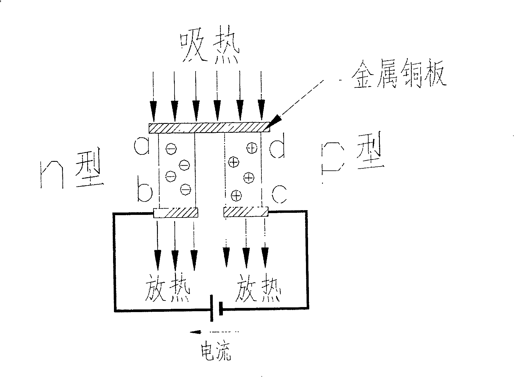
[0017] figure 1 Schematic diagram for the Peltier effect and thermoelectric refrigeration. When a piece of N-type semiconductor material and a piece of P-type semiconductor material are connected into a thermoelectric pair, after a direct current is connected in this circuit, energy transfer can occur, and the current flows from the N-type element to the joint of the P-type element to absorb heat. It becomes the cold end; the joint that flows from the P-type element to the N-type element releases heat and becomes the hot end.

[0018] Introducing a third material into the thermoelectric refrigeration circuit will not change the circuit properties, so copper current leads, high-temperature superconducting current leads and superconducting magnets can be connected in series in the thermoelectric refrigeration circuit.

[0019] The relationship betwee...


PUM


Abstract

The invention is concerned with the current down-lead of the superconductive magnet, includes the copper down-lead (-) and the groupware of the high-temperature superconductive current down-lead (-), the characteristic is: the indoor temperature end of the copper current down-lead (-) connects with a pair of semiconductor cooling groupware (-) in series in order to form combination current down-lead of the semiconductor cooling groupware (-), the copper down-lead (-) and the high-temperature superconductive current down-lead groupware (-);semiconductor cooling groupware (-) consists of the semiconductor cooling element (- ~ -), copper connecting nose (- ~ -) and the copper compacting plate (- ~ -); the invention can decrease the tie-in temperature between the top of the copper down-lead (-) and the copper compacting plate (- ~ -), reduce the leaking heat to the system from the copper down-lead, reduce the cooling need of the first-level cooling head of the cooling machine, and increase the electrify ability of the current down-lead.

Description

technical field [0001] This invention relates to conduction cooled superconducting magnet current leads. Background technique [0002] In the early 1980s, M.O.Hoenig proposed to use a refrigerator to cool NbSn 3 The superconducting magnet was conceived and conceptually designed, but the successful development of the practical conduction cooling superconducting magnet system was a matter of the 1990s, which was mainly due to the new magnetic cold storage material of the refrigerator and the high-temperature superconducting current use of leads. [0003] The conduction cooling superconducting magnet system is mainly composed of superconducting magnet, G-M refrigerator, cryogenic container, current lead, magnet power supply and control components. Its core technology is to directly cool superconducting magnets using a two-stage G-M refrigerator. Compared with the liquid helium soaked superconducting magnet system, it has many advantages such as simple operation, no need for ...

Claims


Application Information

Patent Timeline
Patent Type & Authority Patents(China)
IPC IPC(8): H01F6/04F25B21/02H01L35/28H01B12/16
CPCY02E40/647Y02E40/60
Inventor 赵保志王秋良戴银明宋守森雷沅忠王厚生
Owner INST OF ELECTRICAL ENG CHINESE ACAD OF SCI
Why Eureka
Try Eureka