
Linear guide rail

A technology of linear guides and guides, applied in the field of linear guides, can solve the problems of large friction coefficient of linear guides and low lifespan of guides, and achieve the effects of good follow-up, improved response speed and sensitivity, and convenient disassembly.

Inactive Publication Date: 2009-05-06
浙江斯尼尔导轨有限公司
View PDF4 Cites 0 Cited by
  • Summary
  • Abstract
  • Description
  • Claims
  • Application Information

AI Technical Summary

Problems solved by technology

[0005] The technical problem to be solved by the present invention is to provide a linear guide rail to overcome the shortcomings of the existing linear guide rails such as large friction coefficient and low guide rail life.

Method used


Image

  • Linear guide rail
  • Linear guide rail
  • Linear guide rail

Examples


Embodiment Construction

[0021] Further illustrate the present invention below in conjunction with accompanying drawing.

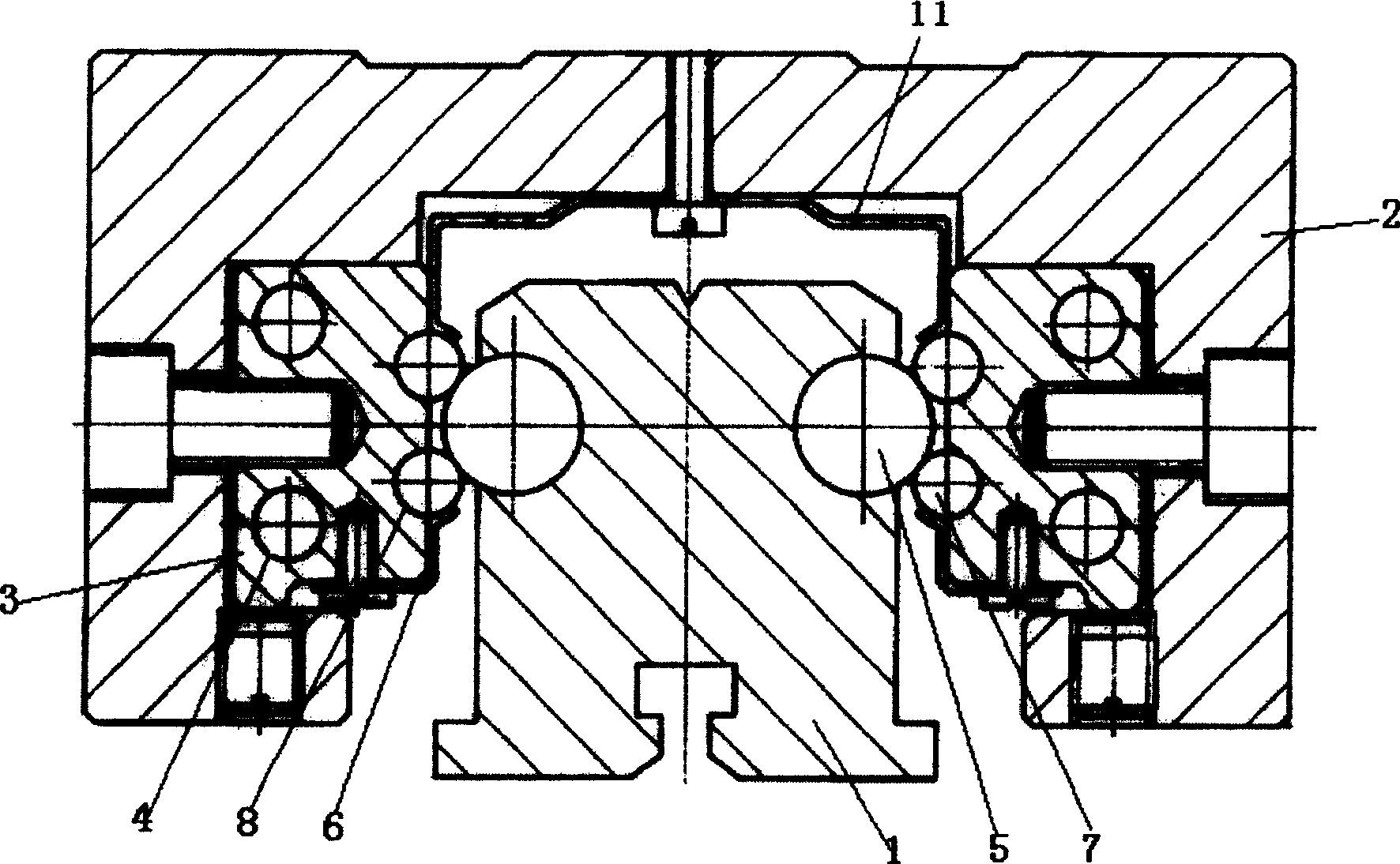
[0022] see figure 1 , the linear guide rail of the present invention includes a guide rail and a slider, and the slider is slidably fixed on the guide rail. The guide rail includes a guide rail main body 1 and a cylindrical guide rail 5; The axis of symmetry is provided with an arc-shaped track groove, and the cylindrical guide track 5 is embedded in the track grooves on both sides of the guide rail main body.

[0023] The slider includes a slider body 2 and bearings.

[0024] The slider main body 2 is a door shape, and grooves are symmetrically arranged on the inner sides of the door frames on both sides of the slider main body

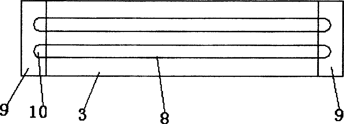
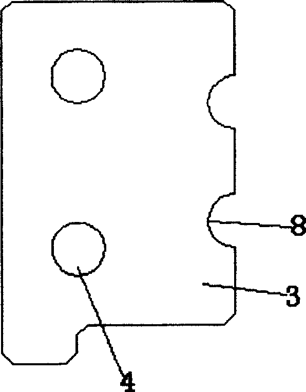
[0025] see figure 1 , figure 2 , image 3 , the bearing includes a bearing main body 3, steel balls 7, and end caps 9, the end caps 9 are fixedly arranged at both ends of the bearing main body 3, and the bearing main body 3 is fixedly arranged in t...


PUM


Abstract

The invention discloses a linear guide rail, which consists of guide rail and slide block, wherein the slide block is fixed on the guide rail; the guide rail contains guide rail body and circular guide orbit; the arc rail groove is set in two sides of guide body at the axle of orbit body centre-line; the relating circular guide orbit is inserted in two sides of orbit groove of guide rail body; the steel ball and steel ball rolling channel are set in the slide block, which is widely used in kinds of precise numerical control machine and machine production management.

Description

technical field [0001] The invention relates to a bearing, in particular to a linear guide rail capable of realizing precise linear motion. Background technique [0002] Linear guide rails are widely used in various precision CNC machine tools and machinery manufacturing industries, and their performance directly determines the accuracy and use effect of CNC machine tools. [0003] Most of the traditional linear guide rails include guide rails and sliders. There are pulleys inside the sliders. The sliders can be slidably fixed on the guide rails. There are pulleys inside the sliders. As a sliding medium, the linear guide rail has simple structure, low production cost and easy replacement. However, its disadvantages cannot be ignored. The main disadvantages are: large frictional resistance, fast wear, large difference between dynamic and static friction coefficients, and easy to crawl at low speeds. The gap is difficult to guarantee, too large a gap affects the rotation acc...

Claims


Application Information

Patent Timeline
Patent Type & Authority Patents(China)
IPC IPC(8): F16C29/04F16C29/12
Inventor 吴敏江
Owner 浙江斯尼尔导轨有限公司
Learn More