
Resetting tool

A tool and nut technology, applied in the field of reset tools, can solve problems such as depth restrictions

Inactive Publication Date: 2009-05-13
SYNTHES GMBH
View PDF7 Cites 0 Cited by
  • Summary
  • Abstract
  • Description
  • Claims
  • Application Information

AI Technical Summary

Problems solved by technology

But its disadvantage is that the depth is limited due to the two different threads provided on the device
Another disadvantage is that the draw nut has to be moved over a large distance via the adjusting thread before reaching the guide (where the draw movement begins)

Method used


Image

  • Resetting tool
  • Resetting tool
  • Resetting tool

Examples


Embodiment Construction

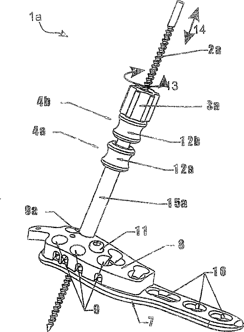
[0028] figure 1 The intended use of the reset tool 1 a is shown. A guide hole 9 a is provided on the sight 8 . Said aimer 8 is fixed on the implant 7 with screws 11 . The implant 7 is plate-shaped and has a plurality of holes 10 through which locking screws pass and fix the bone with the locking screws. The implant 7 remains until the fracture in the body heals. The aimer 8 is instead mounted on the implant 7 only temporarily. The sight 8 has numerous guide holes 9 . Use the guide hole 9 to set the locking screw. Among them, the sight plays the role of guidance and auxiliary positioning. like figure 1As shown, the reset tool 1a is arranged in such a guide hole 9a.

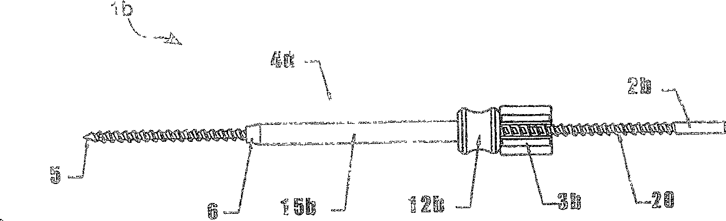
[0029] The reduction tool 1a has a Kirchner bone pulling wire 2a. The Kirchner skeletal pull wire 2a is preferably made of steel. The Kirchner bone puller wire 2 a penetrates at least one catheter 4 . exist figure 1 In the illustrated embodiment two conduits 4a, 4b are provided. The conduit 4 is a casi...


PUM


Abstract

The invention relates to a reduction tool (1a) used for axial movement of a Kirchner wire (2), in particular for use in conjunction with a bone splint implanted to fix a fracture. It has a Kirchner wire which is partially threaded (20). and it has at least one duct (4a, 4b) positioned on a Kirchner wire. A nut (3a) is provided, which has a longitudinal slit and an inner eyelet, so that the nut can be placed on the Kirchner wire and supported on the catheter, wherein the Kirchner wire By turning the nut (3), the inside of the guide tube (4) can be moved in the axial direction (14) relative to the nut (3) and the guide tube (4).

Description

technical field [0001] The invention relates to a reset tool and a nut for a reset tool according to the preambles of claims 1 , 16 and 23 for axial displacement of a Kirchner wire. Background technique [0002] Kirchner wires are often used in fracture fixation. The Kirchner wires are used only for temporary fixation and stabilization, whereas for example bone screws are used to ensure the necessary permanent fixation while the bone is healing. In addition, Kirchner's wire was used in fracture reduction. In this case the Kirchner wire must be removed after reset. [0003] The fracture fixation will be illustrated below with an example of the Less Invasive Stabilization Systems (LISS: Less Invasive Stabilization Systems). This system is characterized by a plate-like implant acting as a so-called internal fixator together with a locking screw. An advantage of this system is that the blood supply to the bone can be maintained under the splint since there is essentially no ...

Claims


Application Information

Patent Timeline
Patent Type & Authority Patents(China)
IPC IPC(8): A61B17/72A61B17/88A61B17/17A61B17/84A61B17/86A61B17/92
CPCA61B17/1735A61B17/866A61B17/8875A61B17/848A61B17/1728A61B17/8665A61B17/92A61B17/58A61B17/88A61B17/72A61B17/82
Inventor 斯特凡·施威尔莱托·巴布斯特奥尔兰多·马尔提纳利
Owner SYNTHES GMBH
Learn More