Method for determining grid rigidity of lead acid battery and device therefor

A lead-acid battery and measuring device technology, applied in the direction of testing the hardness of materials, etc., can solve the problems of increasing the scrap rate of coated panels and production costs, and it is difficult to ensure the stability of the product production process.

Inactive Publication Date: 2009-05-13
FENGFAN
View PDF5 Cites 0 Cited by
  • Summary
  • Abstract
  • Description
  • Claims
  • Application Information

AI Technical Summary

Problems solved by technology

In fact, even high-quality inspectors often have the problem of wrong detection, so that unqualified grids enter the coating process, increasing the scrap rate of coating and production costs, and it is also difficult to ensure the stability of the product production process

Method used


Image

  • Method for determining grid rigidity of lead acid battery and device therefor

Examples


Embodiment Construction

[0016] The method of the invention is suitable for detecting the rigidity of lead-calcium alloy grids or lead-antimony alloy grids used in lead-acid storage batteries. The lead-calcium alloy grid or the lead-antimony alloy grid needs to be effectively hardened after casting. The hardening method can be hardened in a drying room: temperature: 60±10°C, time: 16-24h, or natural hardening for more than 1 week. The rigidity of the hardened grid is detected by the method of the present invention, qualified products enter the plate coating process, and unqualified products are subjected to effective hardening again.

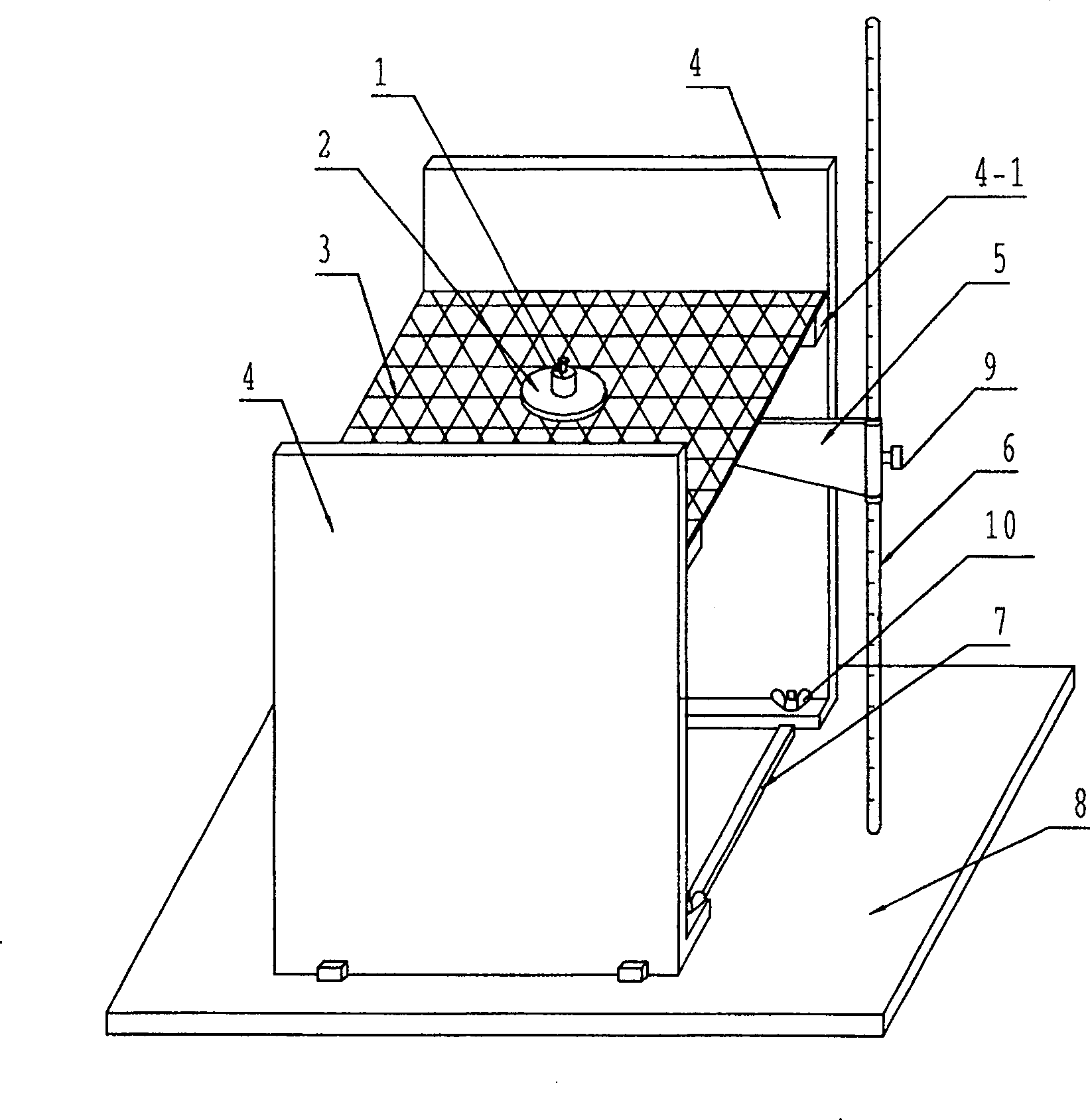
[0017] For the convenience of operation, the present invention designs a device for detecting grid stiffness. see figure 1 The device of the present invention comprises a base 8, a support frame 4, a scale 6, a measuring ruler 5 and a guide rail 7, the guide rail is fixed on the base, and the two support frames are positioned on the guide rails and can move along the g...


PUM

PropertyMeasurementUnit
diameteraaaaaaaaaa

Abstract

The disclosed accumulator plate grid rigidity measurement method comprises: hanging the grid to obtain the distance H1 from grid middle to the base surface; putting weight on grid middle for 20-22s (200g when grid thickness < 2mm, or else 300g), obtaining the distance H2 from grid lowest part to the base surface; calculating the grid bending rate H1-H2 to remove the faulty item larger than the rate. This invention can reduce the waste rate from 0.1% to 0.03%.

Description

technical field [0001] The invention relates to a method for measuring the grid stiffness of a storage battery and a device used in the method, belonging to the technical field of storage batteries. Background technique [0002] The grid is an important component of the battery, and its main functions in the battery are: 1. To support the active material to form a plate; 2. To conduct current. The current is evenly distributed on the active material, so that the battery reaction can proceed smoothly. The grid is cast from an alloy material, and the newly cast grid needs to be effectively hardened to stabilize the structure of the grid, realize the rearrangement of the alloy crystal structure, and improve its mechanical strength. The hardened grid is then squeezed into the grid through the coating process. In this process, if the rigidity of the grid is not enough, many difficulties will be encountered, such as deformation of the raw board, dissatisfaction with plastering or...

Claims


Application Information

Patent Timeline
Patent Type & Authority Patents(China)
IPC IPC(8): G01N3/42
Inventor 吴淳李得良李雪松
Owner FENGFAN
Why Eureka
Try Eureka