Light source structure

A technology of light source and fluorescent material, applied in the field of light source structure that can enhance luminous efficiency, can solve the problems of insufficient luminous efficiency, insufficient contact area between ultraviolet light and fluorescent material, etc.

Inactive Publication Date: 2009-05-13
AU OPTRONICS CORP
View PDF8 Cites 0 Cited by
  • Summary
  • Abstract
  • Description
  • Claims
  • Application Information

AI Technical Summary

Problems solved by technology

[0005] However, even if the current traditional lamp tube is a coiled tube structure, the contact area between ultraviolet rays and fluorescent materials is still not enough, so the luminous efficiency is still obviously insufficient

Method used


Image

  • Light source structure
  • Light source structure
  • Light source structure

Examples


no. 1 example

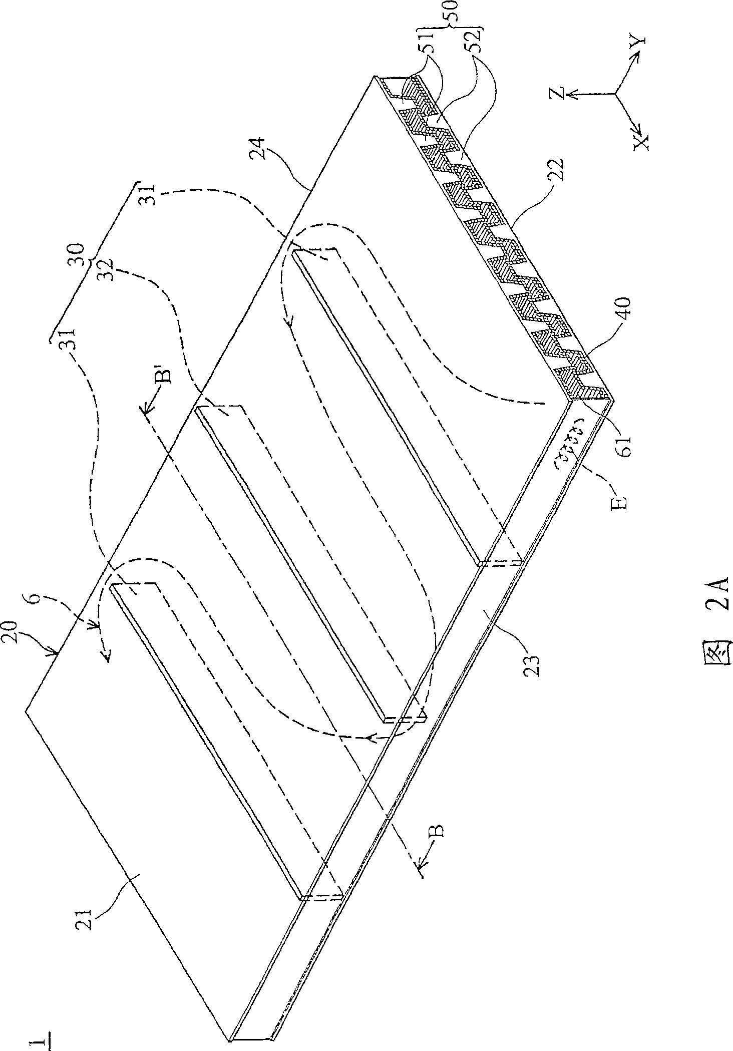
[0058] FIG. 2A is a partial perspective view showing the light source structure 1 according to the first embodiment of the present invention, and FIG. 2B is an exploded perspective view showing multiple curved channels 61 and 62 of the light source structure 1 according to the first embodiment of the present invention. Fig. 2C is a schematic cross-sectional view showing the light source structure 1 viewed along the section line BB' in Fig. 2A. It should be noted that only two curved channels 61 and 62 are marked in FIG. 2B as an example, and the number and length of the curved channels are not limited in the present invention.

[0059] In this embodiment, as shown in FIGS. 2A and 2B , the light source structure 1 is placed on an XY plane, and the light source structure 1 is formed by a hollow shell 20 , positive and negative electrodes and a plurality of protrusions 50 . In order to simplify the illustration, FIG. 2A only shows one of the electrodes E, omitting to show the ele...

no. 2 example

[0067] FIG. 3A is a schematic perspective view showing the light source structure 2 of the second embodiment. FIG. 3B is a schematic plan view showing the light source structure 2 of the second embodiment. FIG. 3C is a schematic cross-sectional view taken along line CC' in FIG. 3A. The light source structure 2 of the second embodiment is formed by a hollow casing 200 , positive or negative electrodes E and a plurality of protrusions 500 . The casing 200 includes a plurality of curved channels 610, a first plate 210, a second plate 220, a first side wall 230, a second side wall 240 and a plurality of partitions 300, and the fluorescent material 400 is arranged in the curved channel 610 the inner wall. The protrusion 500 includes a plurality of first protrusions 510 and second protrusions 520 . In this embodiment, the same parts as those in the first embodiment will not be repeated, but the difference is that: the first protrusion 510 is hollow, and the first protrusion is fo...


PUM


Abstract

A light source structure includes a housing and plurality of projecting parts. The housing includes plural bending passages and plural clapboards. The bending passages are separated by clapboards and are connected with each other in parallel. The projecting parts are disposed in the bending passages.

Description

technical field [0001] The invention relates to a light source structure, in particular to a light source structure capable of enhancing luminous efficiency. Background technique [0002] Generally, a flat fluorescent lamp (Flat Fluorescent Lamp) or a cold cathode fluorescent lamp (Cold Cathode Fluorescent Lamp, CCFL) is one of the main components of the light source in the current light source structure. Fluorescent tube is composed of a hollow glass tube, with positive and negative electrodes (electrodes) at both ends, and mercury (Hg) or fluorescent material (phosphor) is placed in the hollow glass tube, the basic principle is to put High voltage is applied to the positive and negative electrodes at both ends of the lamp tube, and the electrons are ejected from the electrode ends. The electrons are accelerated by the high voltage and collide with the mercury atoms in the tube. Ultraviolet light (UV) with excess energy is released, and the released ultraviolet light is ab...

Claims


Application Information

Patent Timeline
Patent Type & Authority Patents(China)
IPC IPC(8): H01J61/30H01J61/44H01J61/00F21S6/00
Inventor 万祥文苏耀庆
Owner AU OPTRONICS CORP
Why Eureka
Try Eureka