Gravity flow type oil spout mouth detector

A fuel injection nozzle and self-flow technology, which is applied in the field of fuel injection nozzle detectors, can solve the problems of oil blockage, unreachable hydraulic oil, and low work efficiency.

Inactive Publication Date: 2009-05-20
上海运畅机电科技有限公司
View PDF3 Cites 0 Cited by
  • Summary
  • Abstract
  • Description
  • Claims
  • Application Information

AI Technical Summary

Problems solved by technology

[0002] At present, the detectors used to detect fuel injectors in the domestic and foreign markets all adopt the adsorption type. In this structure, the oil storage tank is generally located on the lower side of the oil inlet hole, and the hydraulic pressure of the oil storage tank is connected through the oil pipe. The oil chamber sucks the hydraulic oil into the chamber in one direction in a state similar to a vacuum, and then squeezes out the oil nozzle in one direction with the piston force. After reaching a certain pressure, the fuel injection nozzle is tested. The qualified fuel injection nozzle is used in various For mechanical or internal combustion engines, due to the adsorption method, there is a common problem that the oil circuit is easily blocked, and the hydraulic oil cannot be adsorbed. The hydraulic oil cannot reach the chamber in a vacuum state and work normally. Small, slow oil inlet speed, relatively low work efficiency, and because the hydraulic oil cannot enter the chamber, the piston is squeezed without oil, which may easily cause the piston to be strained. After a long time, the piston will be killed and the detector will be damaged.

Method used


Image

  • Gravity flow type oil spout mouth detector
  • Gravity flow type oil spout mouth detector

Examples


Embodiment Construction

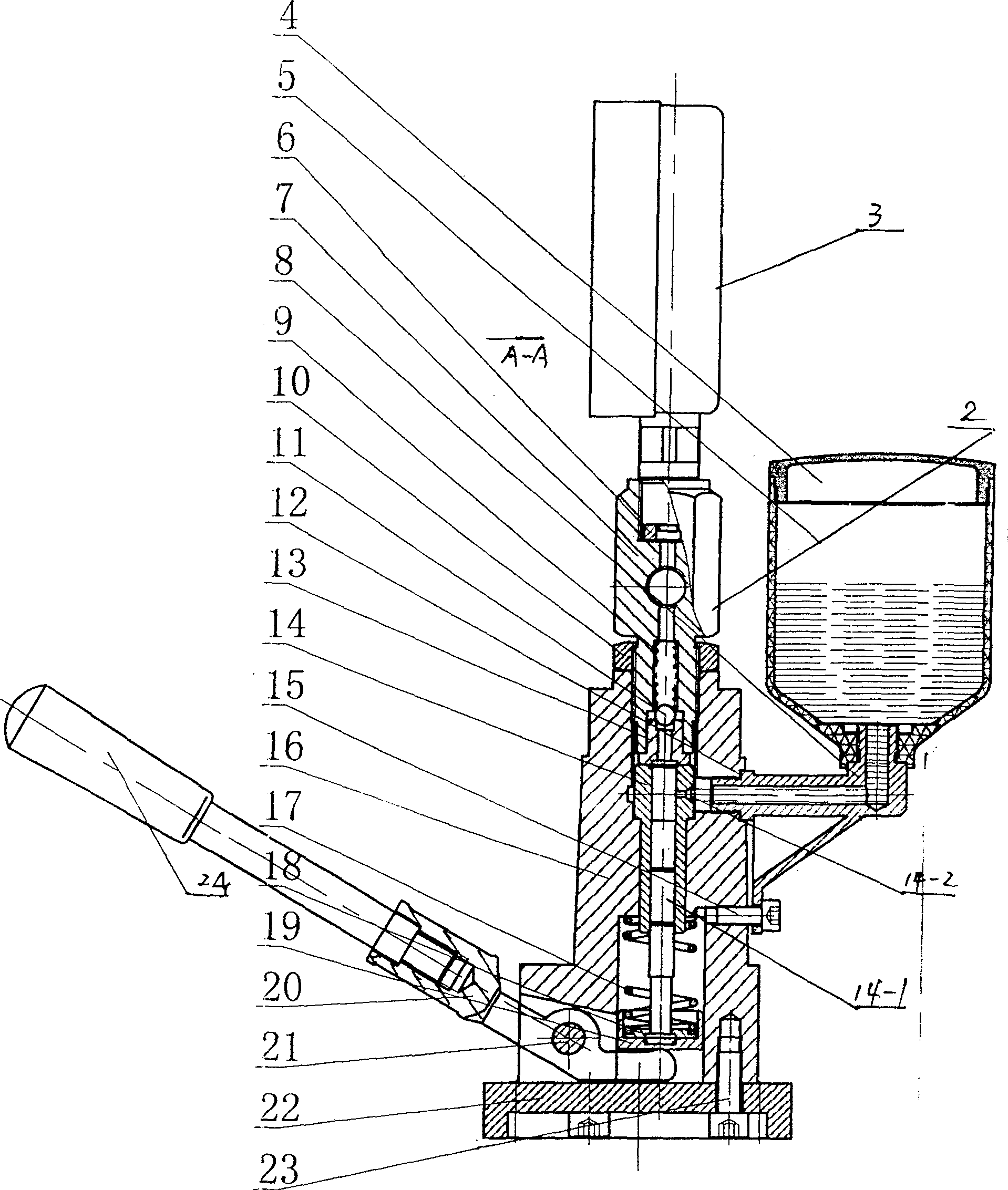
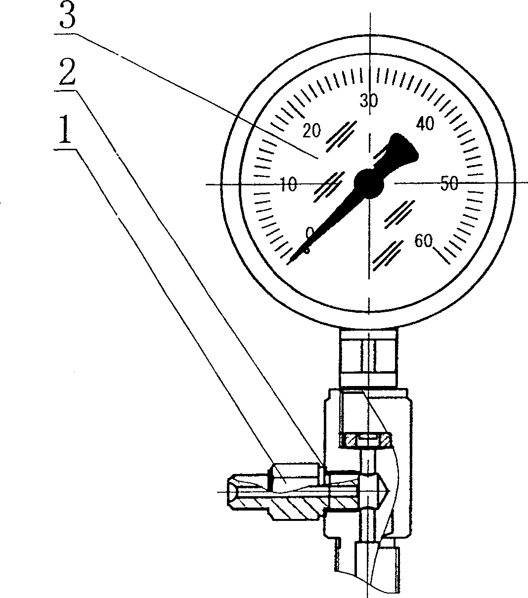
[0007] The present invention will be further described below in conjunction with accompanying drawing:

[0008] See attached figure 1 , 2 , the base 22 and the base 16 are fixed together by screws 23, the pin 21 fixed on the base 16 is flexibly connected to the lever 20, one end of the lever 20 is screwed into the handle 24, and the head of the other end is against the piston tray 19, the piston tray 19 Hold up the piston 14-1, the retaining ring 18 passes through the piston 14-1 and puts it in the piston tray 19 to buckle the piston 14-1, the spring 17 is arranged between the base 16 and the retaining ring 18, and the piston 14-1 is inside The plunger sleeve 14 is fixed in the hole of the machine base 16, and its oil inlet hole 14-2 is aligned with the oil cup seat 8, and the valve seat 13 is placed on the upper end of the plunger sleeve 14 and is pressed tightly and sealed by the screwed pressure gauge joint 7, There is a steel ball 11 on the upper opening of the valve sea...


PUM


Abstract

The invention relates to an artesian ejector detector, which comprises: correcting connector, sealing ring, pressure meter, oil cup cover, oil cup, red copper pad, pressure meter connector, oil cup base, fixing nut, steel ball, sealing pad, valve base, plug muffle, piston, positioning screw, machine base, spring, baffle ring, piston support disc, lever, pin, base, screw, and handle, wherein the oil cup base is connected to the oil cup to be arranged at the upper end of oil inlet; the through hole of oil cup base is Phi 4-20mm. Since the oil cup is at the upper end of oil inlet, it uses artesian method, and it enlarges the oil inlet, the piston will contain oil always, to lubricant the piston and plug muffle, without dead clamp, to improve the reliability and 300% of producing efficiency. The invention can improve the detecting quality and the service life.

Description

1. Technical field: [0001] The self-flowing fuel injector detector relates to the technical field of fuel injector detection, in particular to the technical field of fuel injector detectors, and is applied to the detection of various fuel injectors. 2. Background technology: [0002] At present, the detectors used to detect fuel injectors in the domestic and foreign markets all adopt the adsorption type. In this structure, the oil storage tank is generally located on the lower side of the oil inlet hole, and the hydraulic pressure of the oil storage tank is connected through the oil pipe. The oil chamber sucks the hydraulic oil into the chamber in one direction in a state similar to a vacuum, and then squeezes out the oil nozzle in one direction with the piston force. After reaching a certain pressure, the fuel injection nozzle is tested. The qualified fuel injection nozzle is used in various For mechanical or internal combustion engines, due to the adsorption method, there ...

Claims


Application Information

Patent Timeline
Patent Type & Authority Patents(China)
IPC IPC(8): G01M19/00G01M3/00F02M65/00G01M99/00
Inventor 宋国兴
Owner 上海运畅机电科技有限公司
Why Eureka
Try Eureka