Method and device for measuring transverse pressure for powder flow warm compaction

A transverse pressure and warm pressure forming technology, applied in the field of material processing, can solve the problems of manufacturing technology and its process principle research that have not yet been reported, and achieve the effect of intuitive measurement method, high accuracy and high reliability

Inactive Publication Date: 2009-05-27
SOUTH CHINA UNIV OF TECH
View PDF3 Cites 0 Cited by
  • Summary
  • Abstract
  • Description
  • Claims
  • Application Information

AI Technical Summary

Problems solved by technology

[0004] However, the research on powder flow warm compaction at home and abroad is still in the exploratory stage, and the research on its key manufacturing technology and process principle has not been reported yet.
The lateral pressure measurement device for powder flow warm compaction that can intuitively express and describe the real force of the powder in the lateral direction has not been seen yet.

Method used


Image

  • Method and device for measuring transverse pressure for powder flow warm compaction
  • Method and device for measuring transverse pressure for powder flow warm compaction
  • Method and device for measuring transverse pressure for powder flow warm compaction

Examples


Embodiment 1

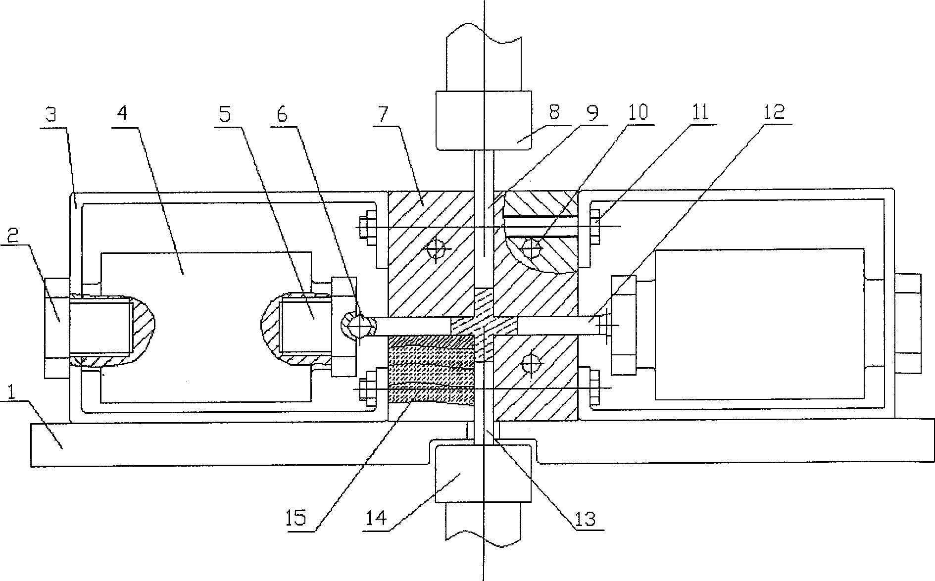
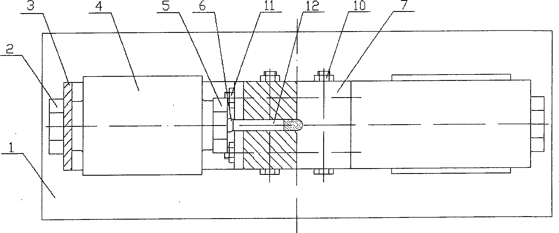
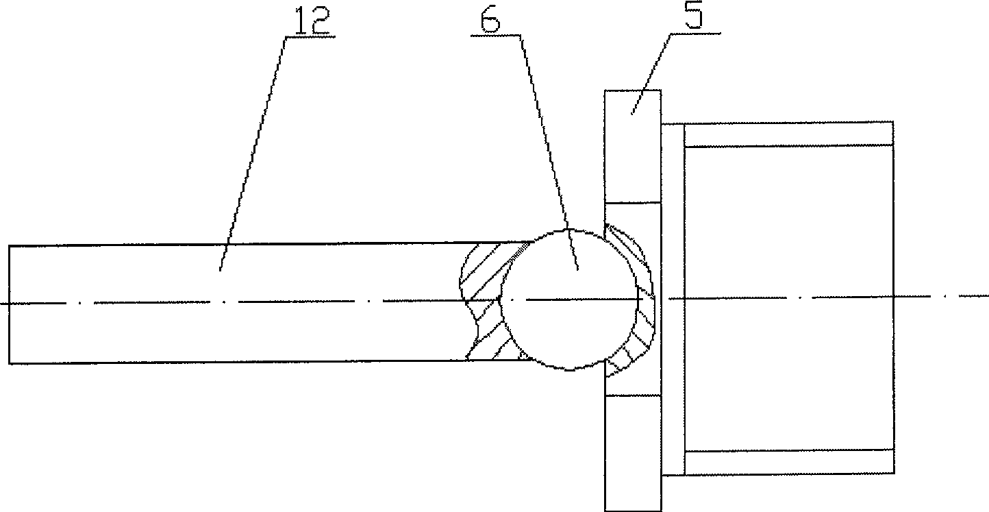
[0022] Such as figure 1 , figure 2 As shown, the powder flow warm pressing forming lateral pressure measuring device is composed of two ejector rods 12, two steel balls 6, two upper and lower die punches 9, 13, two screw ejector columns 5, and two sensor fixing frames installed symmetrically. 3. It is composed of two fixing bolts 2, two pressure sensors 4, a cross mold 7 that can be split into molds for opening and closing, a heating device 15, and a data acquisition card. Such as image 3 Shown is a schematic diagram of the structure of the ejector rod and the screw ejector column connected by steel balls of the measuring device for the lateral pressure of powder flow warm compaction. Clamp the two cross-shaped molds 7 with four sets of bolts 10, and fix the two sensor holders 3 on both sides of the mold cross-shaped mold 7 with four sets of bolts 11; Insert the transverse mold cavity matched with the ejector rod 12 on both sides, screw the two screw ejector columns 5 int...

Embodiment 2

[0027] Such as Figure 4 As shown, in this device, the push rod 12 is directly connected with the screw top column 5, that is, it is not connected by a steel ball. The end face of the push rod 12 is flat and cooperates with the screw top column 5 whose end surface is also flat; the screw top column 5 is connected with the pressure sensor 4 . This embodiment requires that the verticality between the end face of the ejector rod 12 and the centerline of the spiral ejector column 5 and the perpendicularity between the end surface of the spiral ejector column 5 and the center line of the spiral ejector column 5 reach more than 7 levels of perpendicularity, which can avoid causing the ejector rod Tilt to meet the test conditions. In this way, the change of the lateral pressure can also be displayed continuously and directly on the indicator connected to the pressure sensor 4 . All the other implementations are the same as in Example 1.


PUM

PropertyMeasurementUnit
diameteraaaaaaaaaa

Abstract

The invention relates to the field of power metallurgy, specifically the transverse pressure measuring method and device of power flow warm-pressing formation. The measuring method is that one end of the roof rod is inserted into transverse mode control and contacted with the power; the other end is connected with screw shore directly or via steel ball, the transverse position to be measured can be adjusted by revolving screw shore, the screw shore is connected with pressure sensor screw, the variety of transverse pressure can be displayed in indicator continuously and directly. The measuring device includes two roof rods, up plunger and down plunger, two screw shores, two sensor mounts, two fixed bolts, two pressure sensors and cross-die which contains split moulds and matched moulds which are mounted symmetrically. The invention has simple structure, it is easy to produce, low cost; field of application is wide, it can measure the transverse pressure in flow warm-pressing directly, and supplies an important tool to research of lateral flow of the power flow warm-pressing.

Description

technical field [0001] The invention relates to the field of material processing, in particular to a method and a device for measuring lateral pressure in powder flow warm pressing forming. Background technique [0002] Metal powder warm compression forming and injection molding technology are two hot spots in the research and development of powder metallurgy technology. Powder warm compaction is the Hoeganaes company in the United States in 1994 at the International Conference on Powder Metallurgy and Granular Materials (PM 2 TEC94) announced that it is a new process for manufacturing high-density and high-performance iron-based powder metallurgy parts developed on the basis of traditional cold pressing technology. It can produce high-density powder metallurgy parts at a lower cost. Powder metallurgy parts have found an optimal combination between performance and cost. At present, extensive research has been carried out on powder preparation, process optimization, warm pr...

Claims


Application Information

Patent Timeline
Patent Type & Authority Patents(China)
IPC IPC(8): G01L1/00B22F3/02
Inventor 肖志瑜罗术华王军邵明李元元
Owner SOUTH CHINA UNIV OF TECH
Why Eureka
Try Eureka