Micro-heating device used in planar optical waveguide thermo-optic devices and manufacture method therefor

A technology of plane light waves and optical devices, applied in the directions of optical waveguides, optical waveguides, coupling of optical waveguides, instruments, etc., can solve problems such as the limitation of thermo-optic devices, reduce thermal power consumption, simplify the production process, and have a wide range of applications.

Inactive Publication Date: 2009-06-03
ZHEJIANG UNIV
View PDF5 Cites 0 Cited by
  • Summary
  • Abstract
  • Description
  • Claims
  • Application Information

AI Technical Summary

Problems solved by technology

This will impose certain limitations on the development of low-power thermo-optic devices

Method used


Image

  • Micro-heating device used in planar optical waveguide thermo-optic devices and manufacture method therefor
  • Micro-heating device used in planar optical waveguide thermo-optic devices and manufacture method therefor
  • Micro-heating device used in planar optical waveguide thermo-optic devices and manufacture method therefor

Examples


Embodiment Construction

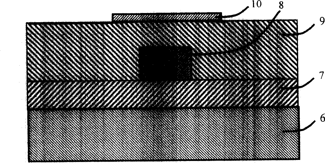
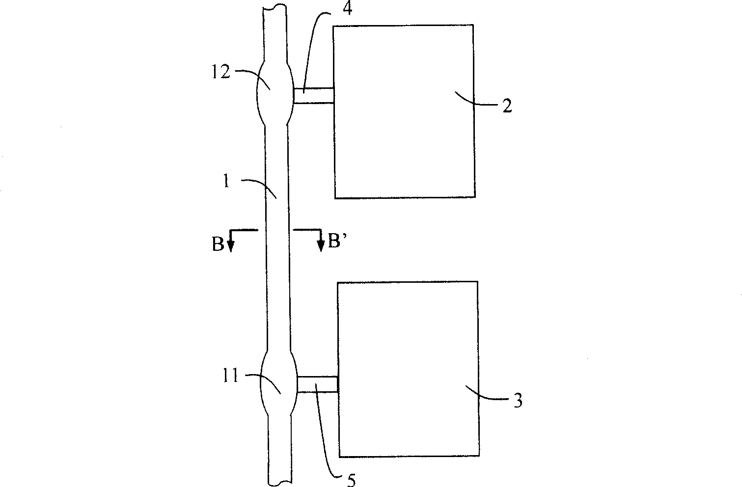
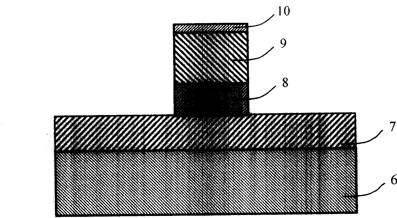
[0021] refer to figure 2 , the micro-heating device for planar optical waveguide thermo-optical devices of the present invention, comprising an optical transmission channel 1, two contact points 2, 3 for connecting to an external power supply, and two connections connecting the optical transmission channel and the two contact points Arm 4, 5. The said optical transmission channel 1 (such as image 3 (shown) consists of a substrate 6 and an isolation layer 7 , a core layer 8 , an upper cladding layer 9 and a thermal electrode thin film 10 deposited on the substrate sequentially from bottom to top. The optical transmission channel 1 is a ridge-type optical waveguide, and the upper cladding layer 9, the hot electrode film 10 and the core layer 8 have the same width. The two contact points 2, 3, the connecting arms 4, 5 and the optical transmission channel 1 have the same layer structure in the height direction (see Figure 4 ).

[0022] In order to reduce the optical power l...


PUM


Abstract

This invention relates to one plane light wave heat conductive part micro heating device, which comprises light transmission channel, two contact point connected to outer power to connect light transmission channel through connection arm, wherein, the light transmission channel is of rip light wave guide orderly depositing isolation layer, chip layer, upper pack layer and heat electrode film on underlay; two contact points and connection arm has same layer structure in height direction. The process method comprises steps of etching to form light transmission channel, connection arm and contact point; then using etch method to form micro heating device.

Description

technical field [0001] The invention relates to the field of planar light waveguide integrated devices, in particular to a micro-heating device for planar light waveguide thermo-optical devices and a preparation method thereof. Background technique [0002] Utilizing the thermo-optic effect is an important means to realize tunable optical devices, such as thermo-optic switches, thermo-optic modulators, tunable optical attenuators, tunable power splitters, and thermo-optic tunable filters. To realize thermo-optic devices, the heating device is very important. The current heating device consists of a light transmission channel, a metal thermode, and two contact points for connecting an external power source. The cross-section of the optical transmission channel is as figure 1 As shown, it is composed of a substrate 6 and an isolation layer 7, a core layer 8, an upper cladding layer 9 and a metal hot electrode film 10 deposited on the substrate in sequence from bottom to top,...

Claims


Application Information

Patent Timeline
Patent Type & Authority Patents(China)
IPC IPC(8): G02B6/12G02B6/35G02F1/313G02F1/00
Inventor 戴道锌
Owner ZHEJIANG UNIV
Why Eureka
Try Eureka