Efficient synthesizing jet-flow excitor

A technology of synthetic jet and exciter, applied in the direction of fluid flow, mechanical equipment, etc., can solve the problems of low efficiency and insufficient power of synthetic jet, and achieve the improvement of the speed of the vortex ring, the output vorticity and the translation speed, and the service life. Effect

Inactive Publication Date: 2009-06-17
BEIHANG UNIV
View PDF5 Cites 0 Cited by
  • Summary
  • Abstract
  • Description
  • Claims
  • Application Information

AI Technical Summary

Problems solved by technology

[0003] The purpose of the invention is to develop a high-efficiency synthetic jet exciter, shorten the jet blowing process, prolong the inhalation process, enhance the output of the vorticity of the exciter, improve the energy consumption ratio, and This solves the problem of insufficient power or low efficiency of synthetic jets in practical applications

Method used


Image

  • Efficient synthesizing jet-flow excitor
  • Efficient synthesizing jet-flow excitor
  • Efficient synthesizing jet-flow excitor

Examples


Embodiment Construction

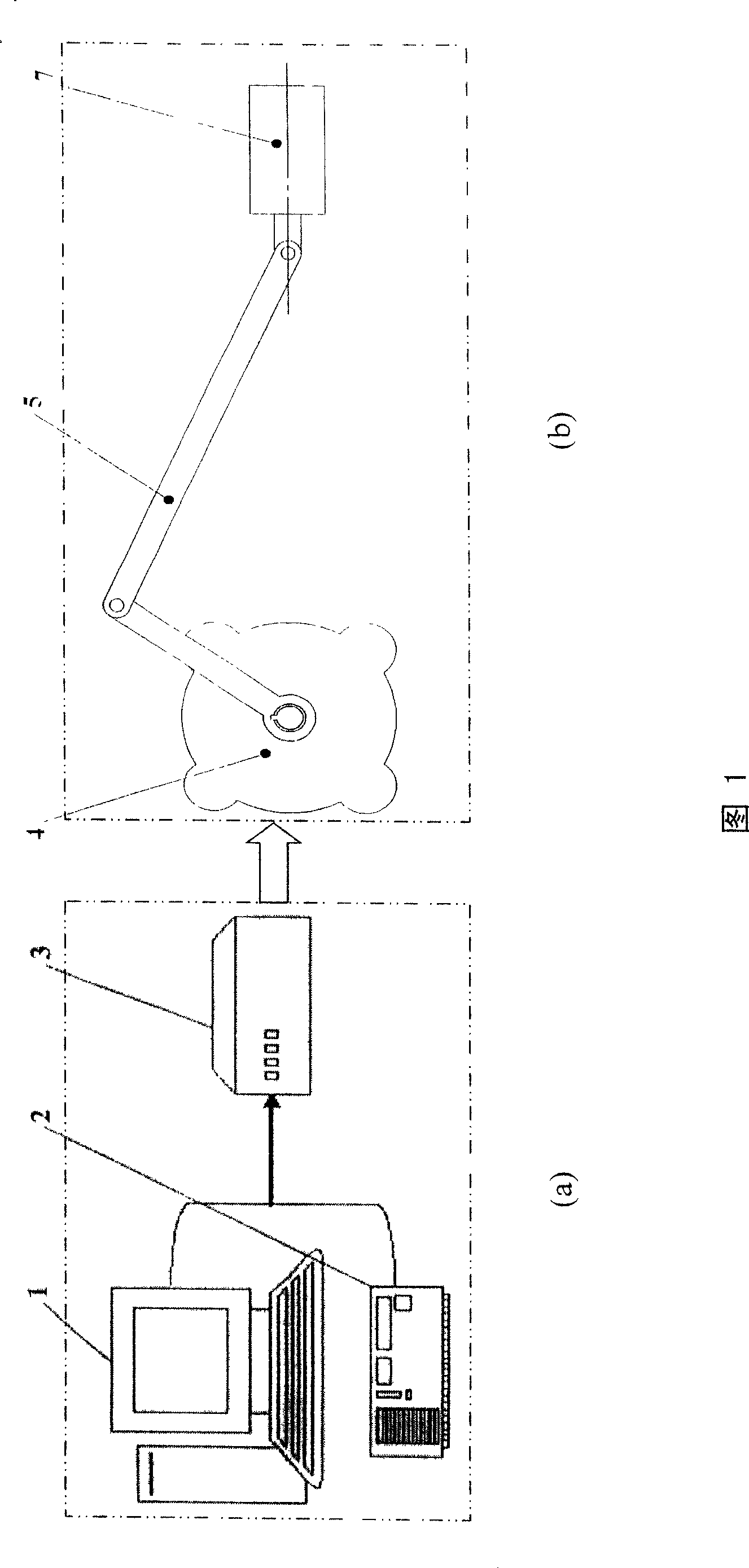
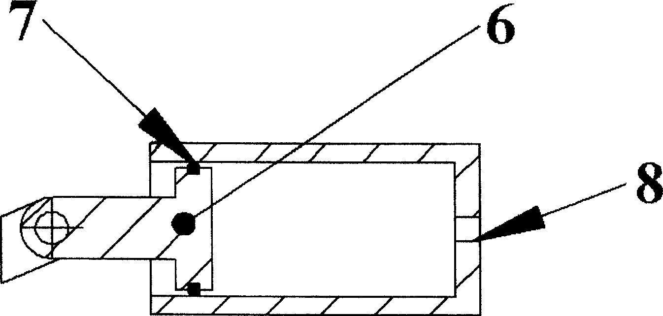
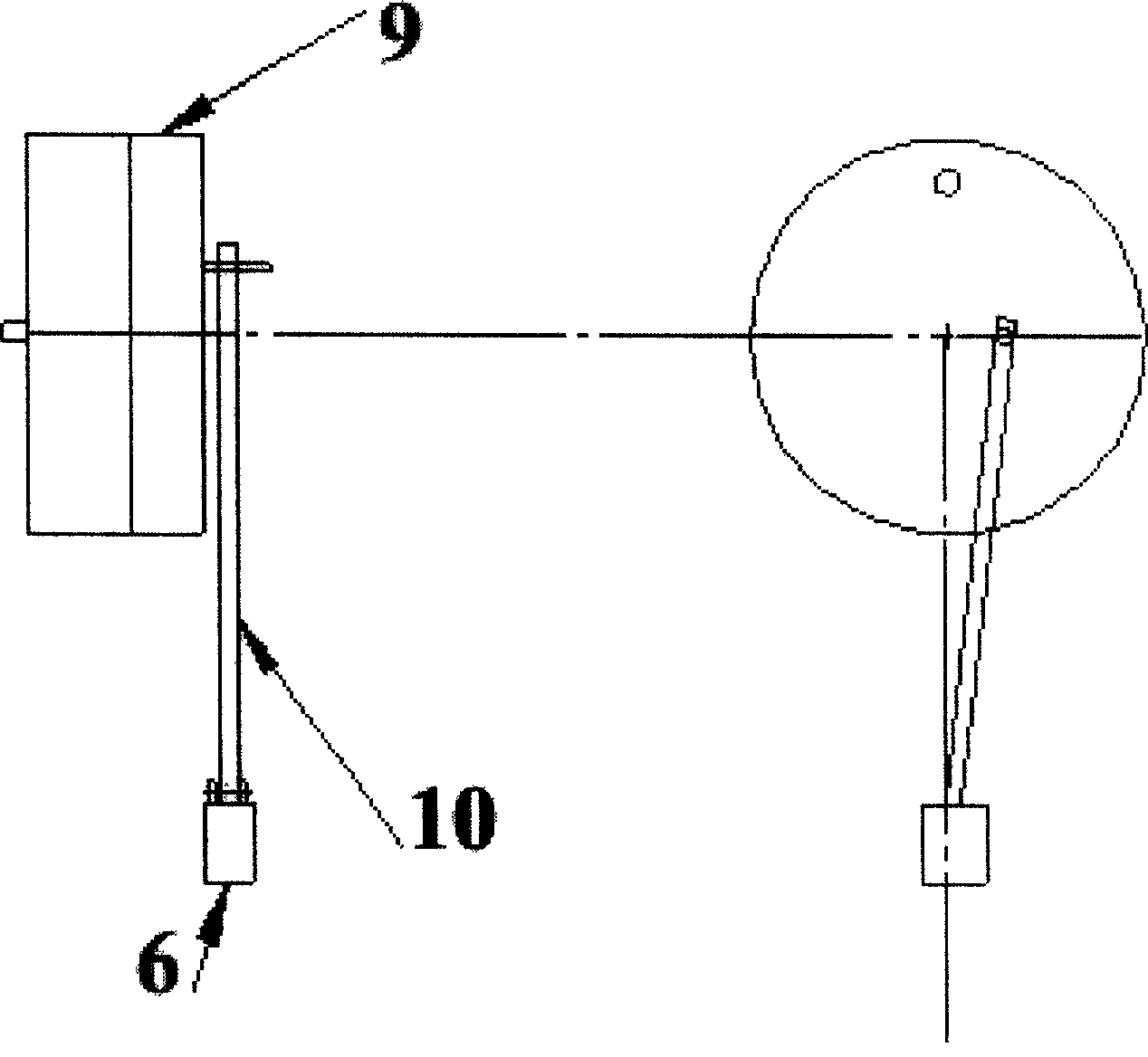
[0026] Please refer to Figure 1, figure 2 and image 3 As shown, the actuator consists of two parts: the control system and the execution system. The role of the control system is to generate a high-efficiency excitation signal to control and monitor the work of the exciter, which specifically includes a microcomputer 1, an A / D conversion card 2, and a programmable controller PLC3. The execution system receives instructions from the control system and works according to specified signals. It specifically includes a servo motor 4 , a centering crank mechanism 5 (including an eccentric disc 9 and a connecting rod 10 ), a vibrator 6 and a cavity 7 . The core of these two parts is the control system, and the core of the control system is the programmable controller PLC3, and the introduction of the programmable controller PLC3 becomes the core technology of the invention.

[0027] The specific connection mode of the high-efficiency synthetic jet exciter is as follows: the micro...


PUM


Abstract

The present invention involves a high efficient synthesis jet driver that can produce high efficient synthesis jet by changing the up-down periodic time of driving signal. The driver includes the control system and implements system. The control includes micro-computer, A / D converter card, PLC programmable logic controller. The implement system includes servo motors, the heart crank mechanism, vibrator, and cavity. The control system produces a high drive signal and control and monitors the work of driver. The implement system receives the order that the control system brings up and work according to the order. The introduction of PLC programmable logic controller that can control the operation of electric engine in the control system make the centering crank structure hurry convolution character and shorten the jet blowing process and lengthen the air-breathing process to produce high efficient synthesis jet.

Description

(1) Technical field: [0001] The invention relates to a high-efficiency synthetic jet actuator, which belongs to the technical field of flow transmission and active control. (two) background technology: [0002] Synthetic jet is a new type of active flow control technology developed in the past ten years. The piston or the piezoelectric film performs reciprocating motion to blow / inhale the gas, forming a series of vortex rings / pairs at the outlet of the cavity, and they merge with each other to form a synthetic jet in the process of expanding outward. The main principle is that during the blowing cycle, the fluid in the chamber forms a vortex ring / pair at the outlet of the chamber under the compression of the piston or vibrating film, and moves away from the outlet of the chamber under their own induction; while in the suction During the air cycle, the vortex ring / pair is far away from the cavity outlet and will not be sucked into the cavity. The mass it blows out is equal ...

Claims


Application Information

Patent Timeline
Patent Type & Authority Patents(China)
IPC IPC(8): F15D1/08
Inventor 张攀峰王晋军徐超军冯立好
Owner BEIHANG UNIV
Why Eureka
Try Eureka