Magnetic encoder

A magnetic encoder and magnetic sensor technology, applied in the field of magnetic encoders, can solve problems such as low power consumption and inability to meet high resolution

Inactive Publication Date: 2009-06-17
HITACHI METALS LTD
View PDF5 Cites 0 Cited by
  • Summary
  • Abstract
  • Description
  • Claims
  • Application Information

AI Technical Summary

Problems solved by technology

SVGMR components are not used in magnetic encoders because they can hardly meet the high resolution required by the market
However, since SVGMR elements exhibit the same magnetoresistance change rate as coupled GMR elements in a relatively small magnetic field region and five to six times the resistance of coupled GMR elements, it is difficult to give up that low electric power can be easily achieved by SVGMR elements Advantages of consumption

Method used


Image

  • Magnetic encoder
  • Magnetic encoder
  • Magnetic encoder

Examples


example 1

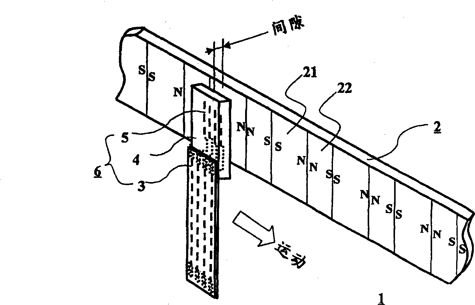
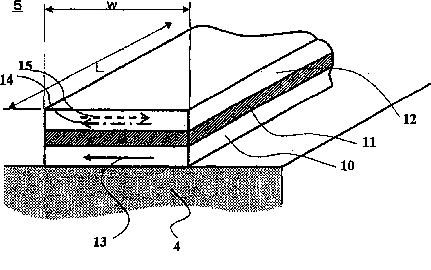
[0042] figure 1 A perspective schematic diagram explaining a magnetic encoder with SVGMR elements is shown. The magnetic encoder 1 consists of a magnetic medium 2 and a magnetic sensor 6 . On the magnetic medium 2, two magnetized regions magnetized opposite to each other, ie, a first magnetized region 21 and a second magnetized region 22, are continuously and alternately arranged along the extending direction of the medium. In the following explanation, it is assumed that the length λl of the first magnetized region 21 is longer than the length λs of the second magnetized region 22 . In the magnetic sensor 6, a plurality of SVGMR elements 5 are formed in a rectangular plane extending perpendicularly to the extending direction of the magnetic medium 2 on the base material 4, and the ends of the SVGMR elements 5 are connected to the flexible printed circuit 3 by wires (not shown). The magnetic medium 2 faces the SVGMR element 5 having a rectangular plane through a predetermine...

example 2

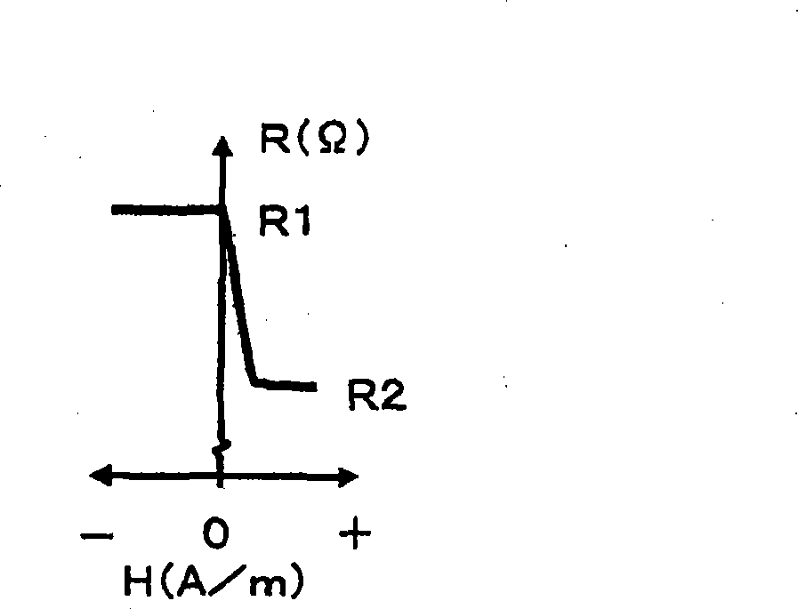
[0047] Referring to FIG. 4, in which the first magnetized region length λl is longer than the second magnetized region length λs on the magnetic medium 2, the operation of the magnetic encoder will be described. Figure 4A The positional relationship between the SVGMR elements 51a to 52b of the magnetic sensor 6 and the magnetic medium 2 is explained, and Figures 4B to 4F A graph of resistance and electrical signal versus location of SVGMR elements 51a to 52b on magnetic medium 2 is shown. The resistance diagrams of the SVGMR element 51a of the first sensor 51, the other SVGMR element 51b of the first sensor 51, the first sensor 51 consisting of SVGMR elements 51a and 51b, and the second sensor 52 consisting of SVGMR elements 52a and 52b are shown respectively exist Figure 4B , 4C , 4D and 4E. In the magnetic sensor 6, four SVGMR elements 51a to 52b are provided on a base material. Each SVGMR element has a cell width w, and the SVGMR elements in each sensor are at a dist...

example 3

[0053] refer to Figures 6A to 6F , a magnetic encoder of Example 3 will be illustrated, with the Figure 4A The magnetic encoder of example 2 in is similar except that the magnetic medium 2 has a first region length that is shorter than a second magnetized region length. Figure 6A The positional relationship between the SVGMR elements 51a to 52b of the magnetic sensor 6 and the magnetic medium 2 is explained, and Figures 6B to 6F A graph of resistance and electrical signal versus location of SVGMR elements 51a to 52b on magnetic medium 2 is shown. The resistance diagrams of the SVGMR element 51a of the first sensor 51, the other SVGMR element 51b of the first sensor 51, the first sensor 51 consisting of SVGMR elements 51a and 51b, and the second sensor 52 consisting of SVGMR elements 52a and 52b are shown respectively exist Figure 6B , 6C , 6D and 6E. In the magnetic sensor 6, four SVGMR elements 51a to 52b are provided on a base material. Each SVGMR element in each ...


PUM

PropertyMeasurementUnit
thicknessaaaaaaaaaa
lengthaaaaaaaaaa
lengthaaaaaaaaaa

Abstract

A magnetic encoder having a magnetic sensor composed of SVGMR elements, in which a signal output with a half of a cycle of magnetic regions on a magnetic medium. The magnetic encoder comprises the magnetic medium, on which first magnetic regions and second magnetic regions are oppositely magnetized along the medium extending and disposed successively and alternately with each other, and the magnetic sensor that has an even number of SVGMR elements and is movable relatively to the medium along the medium extending. Magnetizations of pinned magnetization layers of all the SVGMR elements are directed in a same direction along the medium extending. Each of the even number of SVGMR elements in the magnetic sensor is apart by a half of the sum of a first magnetic region length plus a second magnetic region length from each other along the medium extending, and the even number of SVGMR elements are connected in series so that a cycle of resistance change of the magnetic sensor is a half of a cycle length of the first and the second magnetic regions on the medium and the signal output with high resolution can be obtained.

Description

technical field [0001] The present invention relates to a magnetic encoder using a magnetic sensor with a spin valve type giant magnetoresistance effect film. Background technique [0002] In recent years, magnetic encoders applied to consumer equipment such as small robots, digital cameras, and inkjet printers have been required not only to be inexpensive and miniaturized, but also to have high resolution and excellent gap output characteristics. In other words, a magnetic encoder is required to be miniaturized but not require a processing circuit for doubling the signal frequency, and also maintain a stable output during its operation against gap variations. Furthermore, low electric power consumption is required. [0003] In a conventional magnetic encoder, a magnetoresistor formed of an anisotropic magnetoresistance effect film (hereinafter referred to as "AMR element") is used. AMR elements are widely used because even in a relatively small magnetic field region, the ...

Claims


Application Information

Patent Timeline
Patent Type & Authority Patents(China)
IPC IPC(8): G11B5/02G11B5/09G11B5/39G01R33/09H01L43/08H03K17/97
Inventor 阿部泰典仁平裕治
Owner HITACHI METALS LTD
Why Eureka
Try Eureka