Magnetic encoder
A technology of magnetic encoder and magnetic sensor, applied in the field of magnetic encoder, can solve the problems of low power consumption and high resolution, etc.
- Summary
- Abstract
- Description
- Claims
- Application Information
AI Technical Summary
Problems solved by technology
Method used
Image
Examples
example 1
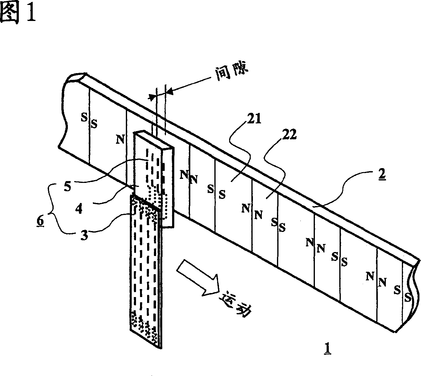
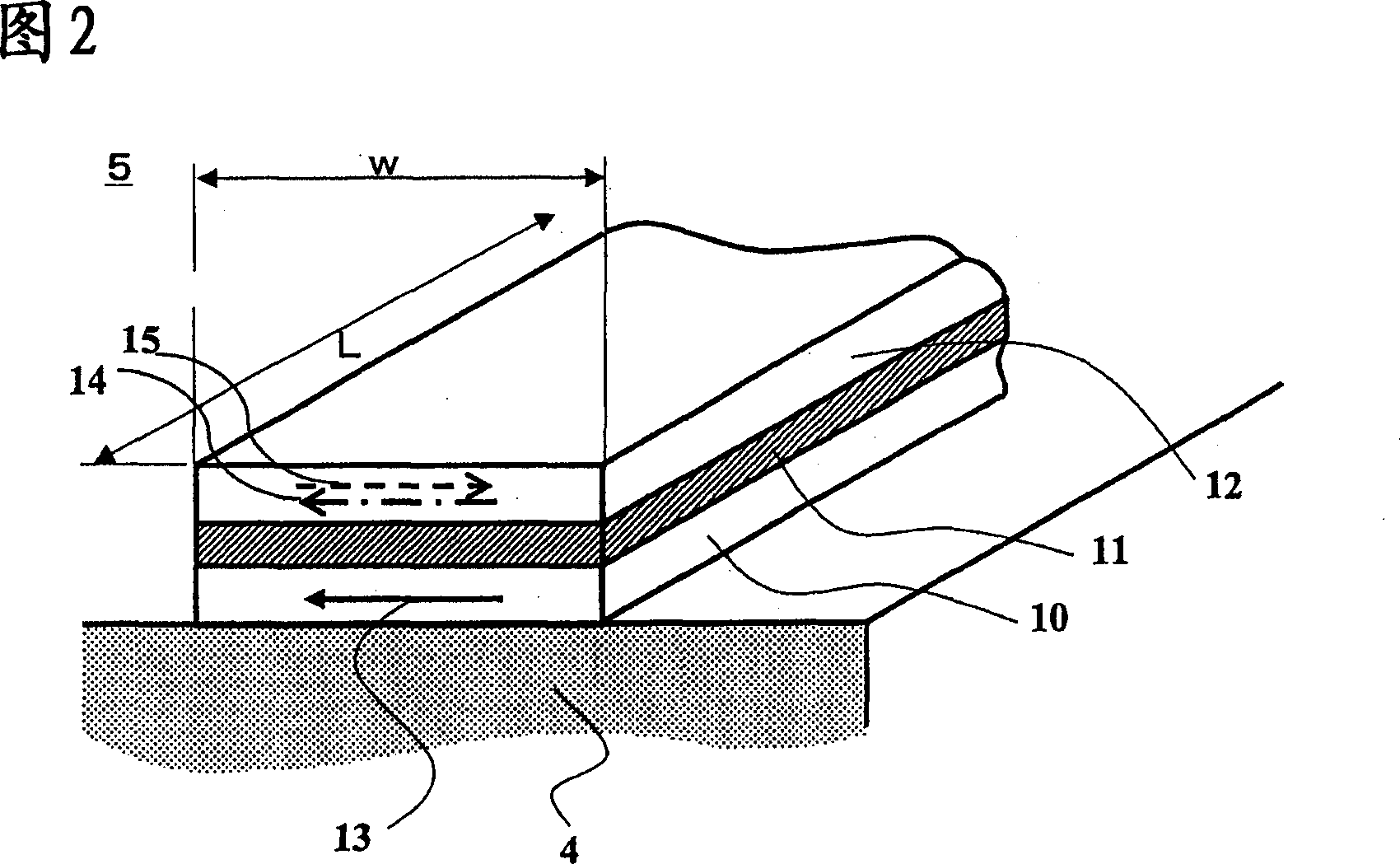
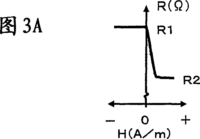
[0042] Figure 1 shows a perspective schematic diagram explaining a magnetic encoder with SVGMR elements. The magnetic encoder 1 consists of a magnetic medium 2 and a magnetic sensor 6 . On the magnetic medium 2, two magnetized regions magnetized opposite to each other, ie, a first magnetized region 21 and a second magnetized region 22, are continuously and alternately arranged along the extending direction of the medium. In the following explanation, it is assumed that the length λl of the first magnetized region 21 is longer than the length λs of the second magnetized region 22 . In the magnetic sensor 6, a plurality of SVGMR elements 5 are formed in a rectangular plane extending perpendicularly to the extending direction of the magnetic medium 2 on the base material 4, and the ends of the SVGMR elements 5 are connected to the flexible printed circuit 3 by wires (not shown). The magnetic medium 2 faces the SVGMR element 5 having a rectangular plane through a predetermined ga...
example 2
[0047] Referring to FIG. 4, in which the first magnetized region length λl is longer than the second magnetized region length λs on the magnetic medium 2, the operation of the magnetic encoder will be described. 4A illustrates the positional relationship between the SVGMR elements 51a to 52b of the magnetic sensor 6 and the magnetic medium 2, and FIGS. The resistance diagrams of the SVGMR element 51a of the first sensor 51, the other SVGMR element 51b of the first sensor 51, the first sensor 51 consisting of SVGMR elements 51a and 51b, and the second sensor 52 consisting of SVGMR elements 52a and 52b are shown respectively In Figures 4B, 4C, 4D and 4E. In the magnetic sensor 6, four SVGMR elements 51a to 52b are provided on a base material. Each SVGMR element has a cell width w, and the SVGMR elements in each sensor are at a distance λ from each other. The second sensor 52 is translated by λ / 2 behind the first sensor 51 . Arrows superimposed on each SVGMR element indicate t...
example 3
[0053] Referring to FIGS. 6A to 6F , a magnetic encoder of Example 3 will be described, which is similar to the magnetic encoder of Example 2 shown in FIG. 4A except that the magnetic medium 2 has a first region length shorter than a second magnetized region length. 6A illustrates the positional relationship between the SVGMR elements 51a to 52b of the magnetic sensor 6 and the magnetic medium 2, and FIGS. The resistance diagrams of the SVGMR element 51a of the first sensor 51, the other SVGMR element 51b of the first sensor 51, the first sensor 51 consisting of SVGMR elements 51a and 51b, and the second sensor 52 consisting of SVGMR elements 52a and 52b are shown respectively In Figures 6B, 6C, 6D and 6E. In the magnetic sensor 6, four SVGMR elements 51a to 52b are provided on a base material. Each SVGMR element in each sensor has a cell width w, and the SVGMR elements in each of the first and second magnetization sensors are at a distance λ from each other. The second sens...
PUM
| Property | Measurement | Unit |
|---|---|---|
| Thickness | aaaaa | aaaaa |
| Gap length | aaaaa | aaaaa |
Abstract
Description
Claims
Application Information
 - R&D
- Intellectual Property
- Life Sciences
- Materials
- Tech Scout
- Unparalleled Data Quality
- Higher Quality Content
- 60% Fewer Hallucinations
Browse by: Latest US Patents, China's latest patents, Technical Efficacy Thesaurus, Application Domain, Technology Topic, Popular Technical Reports.
© 2025 PatSnap. All rights reserved.Legal|Privacy policy|Modern Slavery Act Transparency Statement|Sitemap|About US| Contact US: help@patsnap.com


