Method and device for measuring voltage

A measuring device and a technology for measuring voltage, which are applied in the direction of measuring devices, measuring current/voltage, measuring electrical variables, etc., can solve the problems of inaccurate measurement results and the use of accurate voltages, etc.

Active Publication Date: 2009-07-01
SIEMENS AG
View PDF8 Cites 0 Cited by
  • Summary
  • Abstract
  • Description
  • Claims
  • Application Information

AI Technical Summary

Problems solved by technology

However, at present such capacitive transformers are generally only used to determine the presence or absence of a voltage of a certain minimum magnitude in the conductors of the current distribution network using the displacement current of the high-voltage coupling capacitor, because the obtained measurement results are partly inaccurate, so they are only used to determine the presence of voltage, not for determining the exact magnitude of the voltage

Method used


Image

  • Method and device for measuring voltage
  • Method and device for measuring voltage
  • Method and device for measuring voltage

Examples


Embodiment Construction

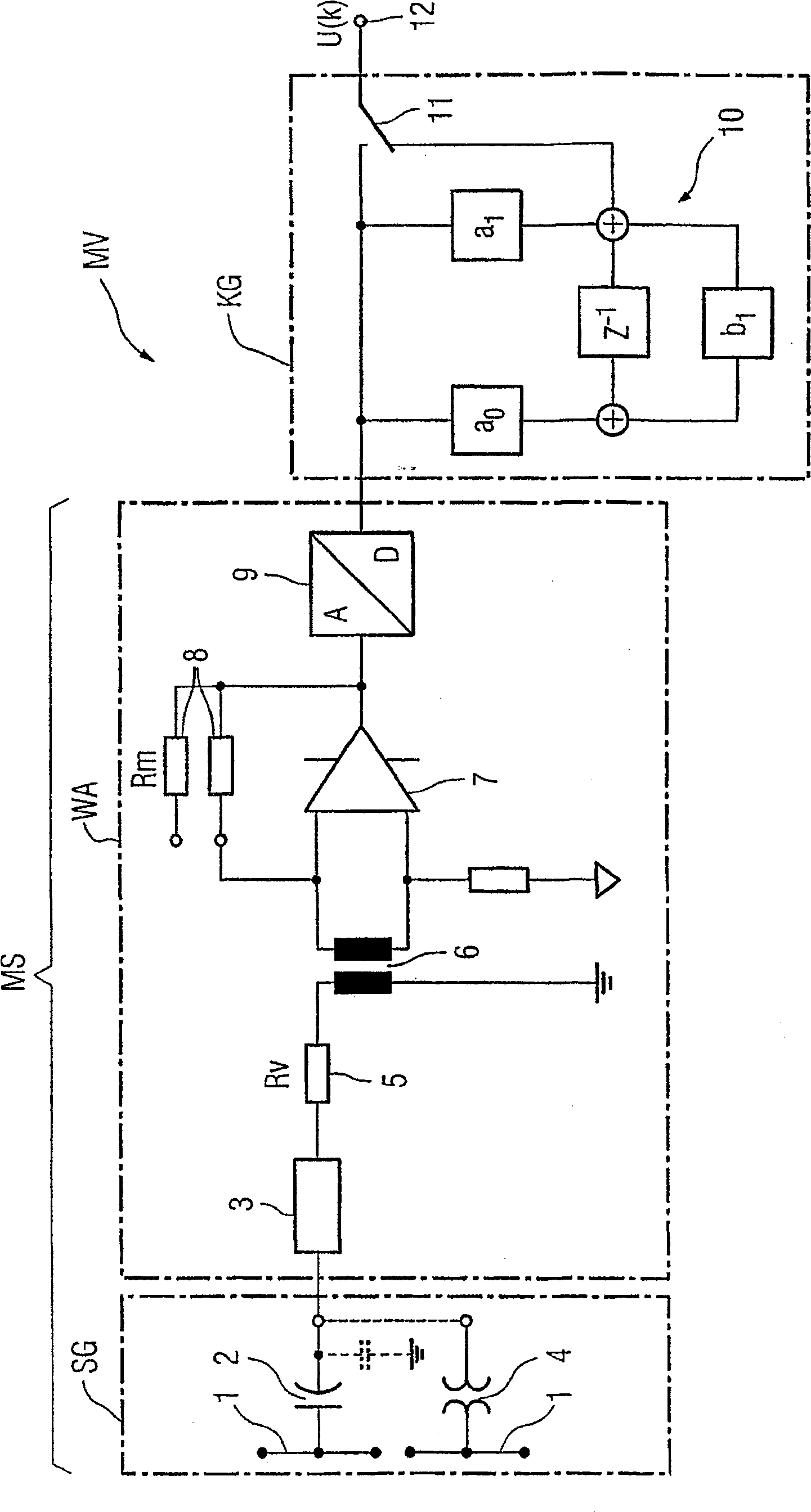
[0027] The current conductors 1 of the current distribution network form the electrodes of a capacitive transformer as a voltage transmitter SG in the form of a high-voltage coupling capacitor 2 . A further electrode of the coupling capacitor 2 , which is preferably electrically isolated from the current line 1 , surrounds the current line 1 in a ring and is connected to the input 3 of the processing unit WA of the measuring device MV. Similarly, other forms of capacitive transformers can also be used as the voltage transmitter SG. As shown, the capacitive transformer may alternatively be a capacitive voltage divider whose low voltage capacitors are shown in dashed lines in the figure. However, it does not necessarily have to be implemented as a capacitive voltage divider, but instead the secondary winding of the inductive transformer 4 connected to the current line 1 on the primary side and the input 3 of the further processing device WA, shown with dotted lines connect. As...


PUM


Abstract

The invention relates to a method for measuring voltage at the location of a current distribution network by means of a measuring circuit (MS) having a voltage transmitter (SG) coupled to a conductor (1) of the grid and connected to the voltage transmitter A further processing device (WA) connected to the device (SG) outputs the measured voltage value as an output signal at the output of the measuring circuit. In order to obtain precise voltage measurements with such a method independently of the type of voltage transmitter (SG) chosen, the invention proposes to obtain correct measurements by means of a Equalizer (KG) to correct the output signal of the measurement circuit (MS). The invention also relates to a measuring device (MV) for carrying out the method.

Description

technical field [0001] The invention relates to a method for measuring voltage at the location of a current distribution network by means of a measuring circuit having a voltage transmitter coupled to a current-carrying conductor of the grid and a further processing device connected to the voltage transmitter, in which The output of the measuring circuit outputs the measured voltage value as an output signal. The invention also relates to a measuring device for carrying out the method. Background technique [0002] For protection and control purposes, currently used devices exhibiting direction-independent overcurrent protection are used in current distribution networks, preferably in the voltage range of 6-20 kV. This is sufficient for power grids with central energy supply in which the direction of the current flow is predetermined. However, in the case of a decentralized energy supply, the response of the protective device also requires the detection of the direction of...

Claims


Application Information

Patent Timeline
Patent Type & Authority Patents(China)
IPC IPC(8): G01R15/16G01R15/18G01R19/25
CPCG01R15/16G01R19/2513G01R15/18
Inventor 安德烈亚斯·朱里希
Owner SIEMENS AG
Why Eureka
Try Eureka