Laser beam welding method and apparatus

A laser beam and equipment technology, applied in laser welding equipment, welding equipment, metal processing equipment, etc., can solve the problems of low productivity, the contact surface of overlapping plates that cannot be welded, and the complicated structure of the welding system, so as to improve productivity, high efficiency and fast Effects of Welding, Simple Processes and Arrangements

Inactive Publication Date: 2009-07-15
HONDA MOTOR CO LTD
View PDF8 Cites 0 Cited by
  • Summary
  • Abstract
  • Description
  • Claims
  • Application Information

AI Technical Summary

Problems solved by technology

The welding process according to prior art 2 consists of multiple welding steps and has low productivity since three plates have to be irradiated with two laser beams applied in different directions
[0017] With prior art 3, the welding system is structurally complicated, and since it is necessary to move the laser beam welding machine 7a along a Z-shaped pattern, the welding system is also structurally and controllly complicated, and it may not be possible to weld metals having different thicknesses. The contact surface of the overlapping plate with the material

Method used


Image

  • Laser beam welding method and apparatus
  • Laser beam welding method and apparatus
  • Laser beam welding method and apparatus

Examples


Embodiment Construction

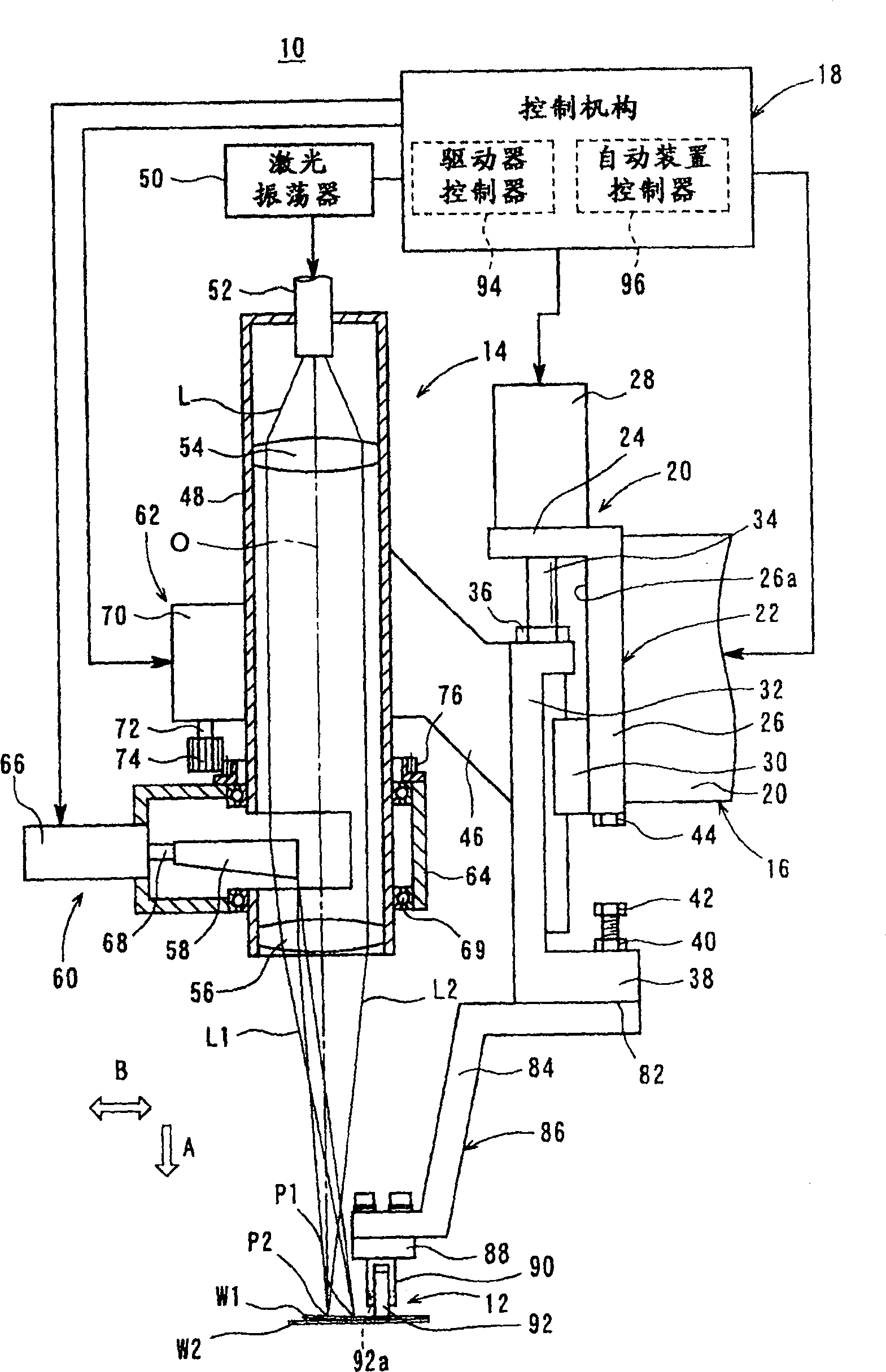
[0048] figure 1 The laser beam welding apparatus 10 performing the laser beam welding method according to the first embodiment of the present invention is shown in side view, partial sectional view and block diagram.

[0049] The laser beam welding apparatus 10 is not limited to one particular use, but may be used for welding galvanized steel sheets W1, W2 such as roof panels of motor vehicles.

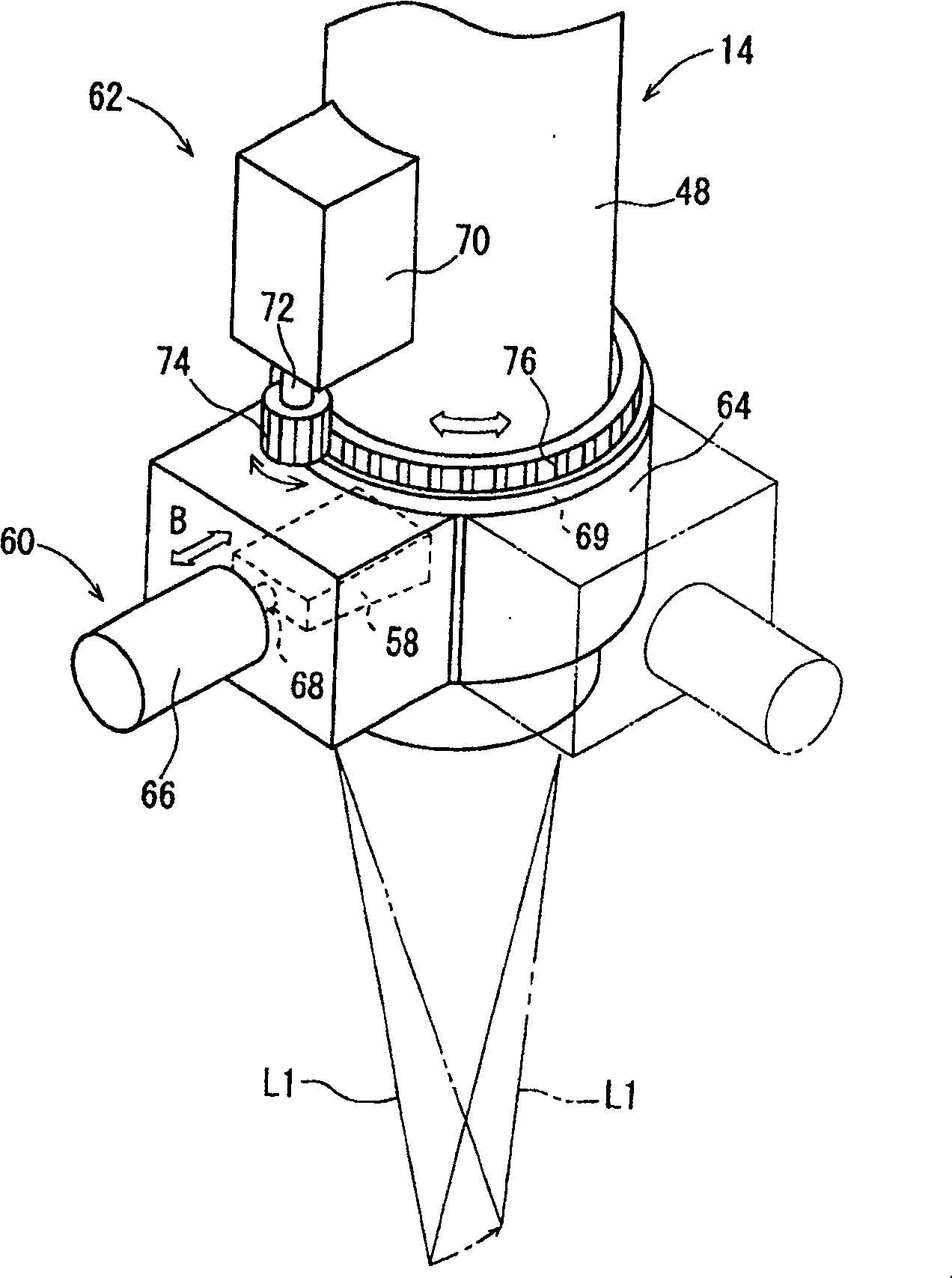
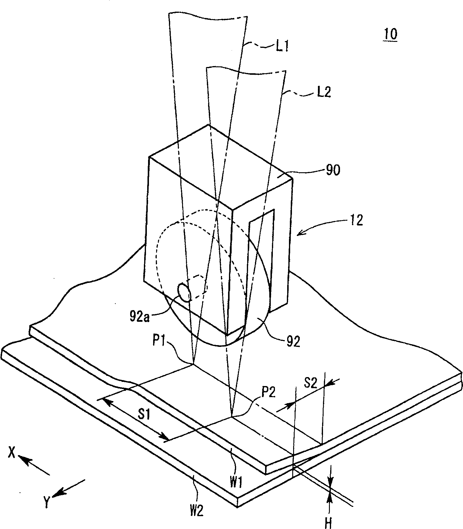
[0050] The laser beam welding equipment 10 includes a holding mechanism 12, a laser beam applying mechanism 14, a mechanical arm (moving mechanism) 16, and a control mechanism 18, wherein the holding mechanism 12 is used to position and hold the welding areas of the steel plates W1, W2, and the laser beam The beam applying mechanism 14 is used to apply the first laser beam L1 to the heating area P1 of the steel plate W1 near the holding mechanism 12 to heat the heating area P1 and to apply the second laser beam L2 to the area separated from the first laser beam L1 by a given distance...


PUM


Abstract

PROBLEM TO BE SOLVED: To enable the simple and quick execution of a laser welding work and the improvement of its productivity. SOLUTION: A heating position P1 of a steel plate W1 is irradiated with a first laser beam L1 in such a state that the steel plate W1 and a steel plate W2 are positioned and held via a holding mechanism 12, so that the steel plate W1 is separated from a steel plate W2 by a prescribed gap. On the other hand, a welding position P2 is irradiated with a second laser beam L2 so that the steel plate W1 and W2 are welded. At that time, the steel plate W1, which is irradiated with the first laser beam L1, is kept in a non-molten state and plastically deformed by setting the heat input, the moving speed, and the condensed beam diameter of the first laser beam L1.

Description

[0001] The present invention is a divisional application of the Chinese invention patent application number 02808842.5 (PCT / JP02 / 04076) and the title of the invention "laser beam welding method and equipment". technical field [0002] The present invention relates to a method and apparatus for welding together overlapping areas of a plurality of plates, each having a base metal coated with a layer thereof, by applying a laser beam to the overlapping areas of the plates. A metal having a melting point lower than the melting point of the base metal. Background technique [0003] Japanese Patent Application No. 3115456 (hereinafter referred to as "Prior Art 1") discloses a known laser beam welding process for welding two mutually overlapping plates each having a base metal , the base metal is coated with a metal having a melting point lower than the melting point of the base metal. [0004] In accordance with the disclosed laser beam welding process, two galvanized steel sheet...

Claims


Application Information

Patent Timeline
Patent Type & Authority Patents(China)
IPC IPC(8): B23K26/067B23K26/24B23K26/42B23K26/00B23K26/21B23K26/02B23K26/064B23K103/04B23K103/16
Inventor 小田幸治深井直树北川纯田边顺也大塚启示
Owner HONDA MOTOR CO LTD
Why Eureka
Try Eureka