Reduced bidirectional strength closed high temperature ball valve

A high temperature, ball valve technology, used in valve devices, cocks including cut-off devices, engine components, etc., can solve problems such as inconvenience for widespread adoption, inconvenience for re-installation of valve actuators, leakage, etc.

Inactive Publication Date: 2009-07-15
赵明
View PDF7 Cites 0 Cited by
  • Summary
  • Abstract
  • Description
  • Claims
  • Application Information

AI Technical Summary

Problems solved by technology

[0006] 4. The sealing surface of the ball valve also has friction during rotation, causing wear and leakage.
[0010] In the above structure, when the wedge-shaped ball is disengaged from the ball petal, the ball petal will follow and move due to the large extrusion force and friction force. The current structure only relies on the left and right sealing surfaces (protruding about ≥ 2.5mm after surfacing) If the upper side is not too large to block, it is easy to cause the valve to be stuck. It is necessary to add an upper adjustment sleeve to prevent it from being stuck, and to improve the reliability so that the valve can be widely used.
In addition, from the perspective of structural layout, the program sleeve that controls the wedge-shaped ball to move up and down and rotate 90° is located above the valve body, which makes the upper structure complicated and it is inconvenient to install valve actuators, etc.
This layout is especially inconvenient to be widely used on small and medium-sized ball valves

Method used


Image

  • Reduced bidirectional strength closed high temperature ball valve
  • Reduced bidirectional strength closed high temperature ball valve

Examples


Embodiment Construction

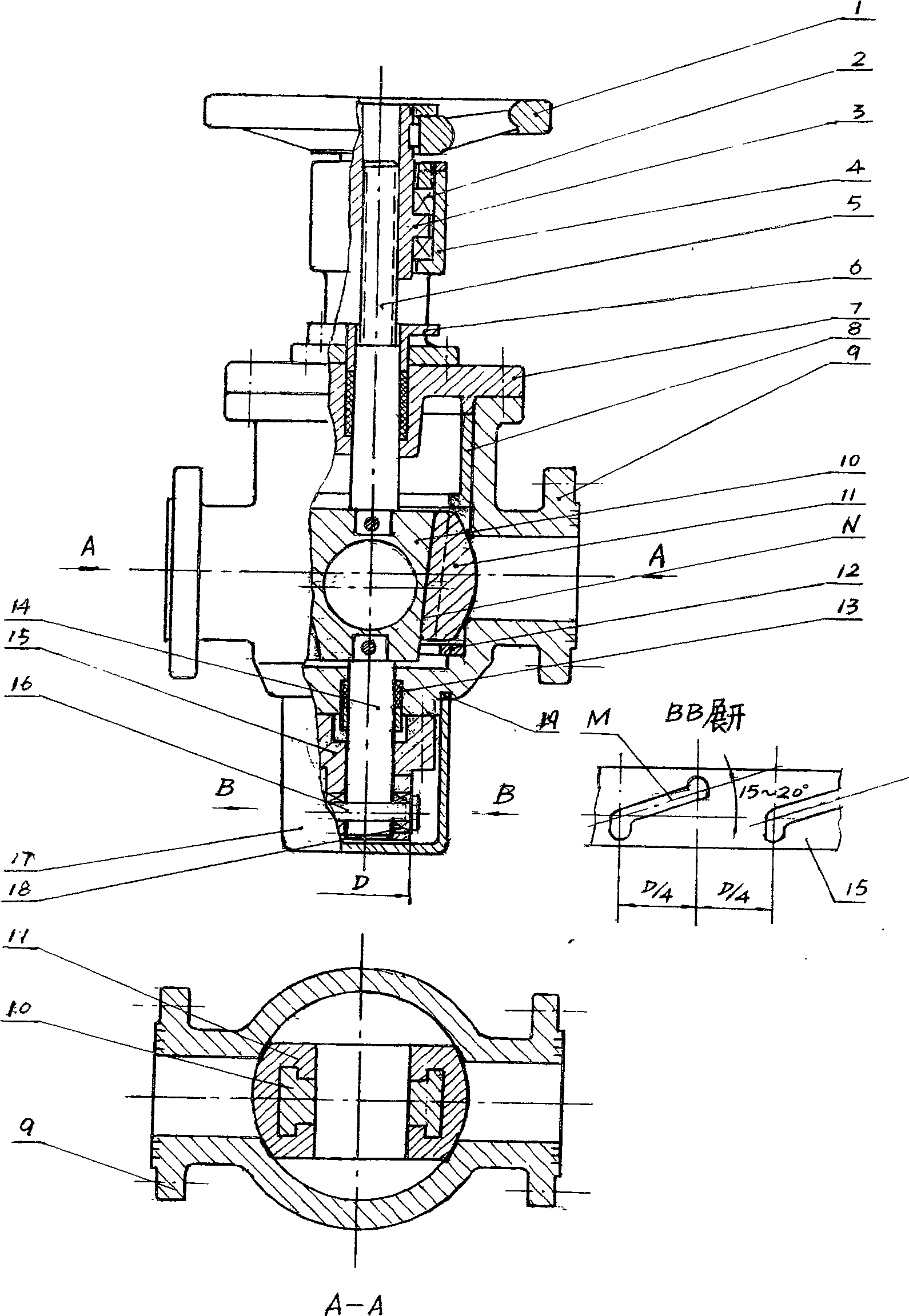
[0019] In the following, specific examples will be combined to describe the implementation in detail. as attached figure 1 In the structure shown, the flange hole diameter of the valve body 9 is φ50, the applicable nominal pressure is 6.3Mpa, the airtight test is 0.6Mpa, the applicable temperature is 400°-450°C, and it is suitable for transporting sulfur-containing medium.

[0020] According to the structure shown in the figure, when the handwheel 1 is turned, the upper valve stem 5 fixed on the upper side of the three components of the sphere is driven by the thread to displace through the rotation of the copper nut 3 supported in the bearing shell 4 . Meanwhile, cross pin and roller assembly 16,18 are arranged on lower valve stem 14, roll in the groove of program sleeve 15. According to the program setting, it can be used as a three-stage working program opening and closing valve with a straight line up and down and a 90° rotation in the middle.

[0021] The three-ball ass...


PUM


Abstract

This simplification type two-way strong-tight high-temperature ball valve pays attention to the simplification of the structure and the reliability of the valve work. Three components of the ball are installed in the spherical shell, the wedge-shaped ball is in the center, and the left and right balls are connected to form a ball with a T-shaped chute; the upper and lower valve stems are fixedly connected with the wedge-shaped ball for positioning and 90° rotation; The nut and bearing assembly are on the upper side of the valve body and are opened and closed by the rotation of the hand wheel. The sealing surface is surfacing hard seal, which is used for high temperature and high pressure corrosive media. There is no friction between the sealing surfaces during the opening process, the service life is long, the required torque is small, and the opening and closing time is short. The simplification of the structure is because the program sleeve is arranged on the lower side of the valve body, which not only simplifies the structure of the upper side of the valve, but also saves the large flange on the lower side of the valve body itself and the corresponding connecting parts. Squeeze the ball flap from the wedge-shaped ball, and when it is in a sealed state, during the process of turning into opening, because there is a large positive pressure on the slope between each other, it will cause the valve to be stuck because it cannot be disengaged. Set the upper positioning sleeve to block the ball. The disc follows the upward movement, so that the valve works reliably, and it is beneficial to be widely used in small and medium-sized valves to replace straight-stroke gate valves and ball valves with fixed balls, and has a good market prospect.

Description

1. Technical field [0001] The invention relates to a ball valve, which can expand the warp by means of the ball disc to achieve a forced two-way hard seal, which is suitable for high temperature and high pressure in petrochemical; The program process is controlled by a bottom-mounted program set, which simplifies the structure of the valve and facilitates the manufacture of ball valves. 2. Background technology [0002] 1. According to the market share ranking of the American Valve Manufacturers Association (vale Manufacturer Associate VMA), "ball valves account for the largest percentage, accounting for 54.2% of the total, with sales of 565.5 (million US dollars). In addition, according to the academic "Petrochemical Investment and Construction" The exchange text pointed out: "The valve core of the ball valve is a spherical body with a round hole. When the valve is in the open position, the fluid is allowed to flow through, and the spherical shape is turned 90° to cut off t...

Claims


Application Information

Patent Timeline
Patent Type & Authority Patents(China)
IPC IPC(8): F16K5/06
Inventor 赵明
Owner 赵明
Why Eureka
Try Eureka