Supercharge Your Innovation With Domain-Expert AI Agents!

Power source managing method of central processing unit

A central processing unit, power management technology, used in data processing power and other directions

Active Publication Date: 2009-07-15
VIA TECH INC
View PDF4 Cites 0 Cited by
  • Summary
  • Abstract
  • Description
  • Claims
  • Application Information

AI Technical Summary

Problems solved by technology

[0008] The purpose of the present invention is to overcome the defects of the existing central processing unit power management method and provide a new central processing unit power management method. The technical problem to be solved is to make the central processing unit unable to spy on events When the peripheral device of the computer system sends out the bus master signal, it will drive the central processing unit to enter the dormant state where the event can be peeped, so that the bus master signal can be transmitted to the central processing unit, so that the central processing unit can process the bus master. Controller signal requirements, in order to achieve the purpose of saving power, which is more suitable for practical

Method used


Image

  • Power source managing method of central processing unit
  • Power source managing method of central processing unit
  • Power source managing method of central processing unit

Examples


Embodiment Construction

[0046] In order to further explain the technology and effect of the present invention to achieve the intended purpose of the invention, below in conjunction with the accompanying drawings and preferred embodiments, the specific implementation methods, methods, Steps, features and effects thereof are described in detail below.

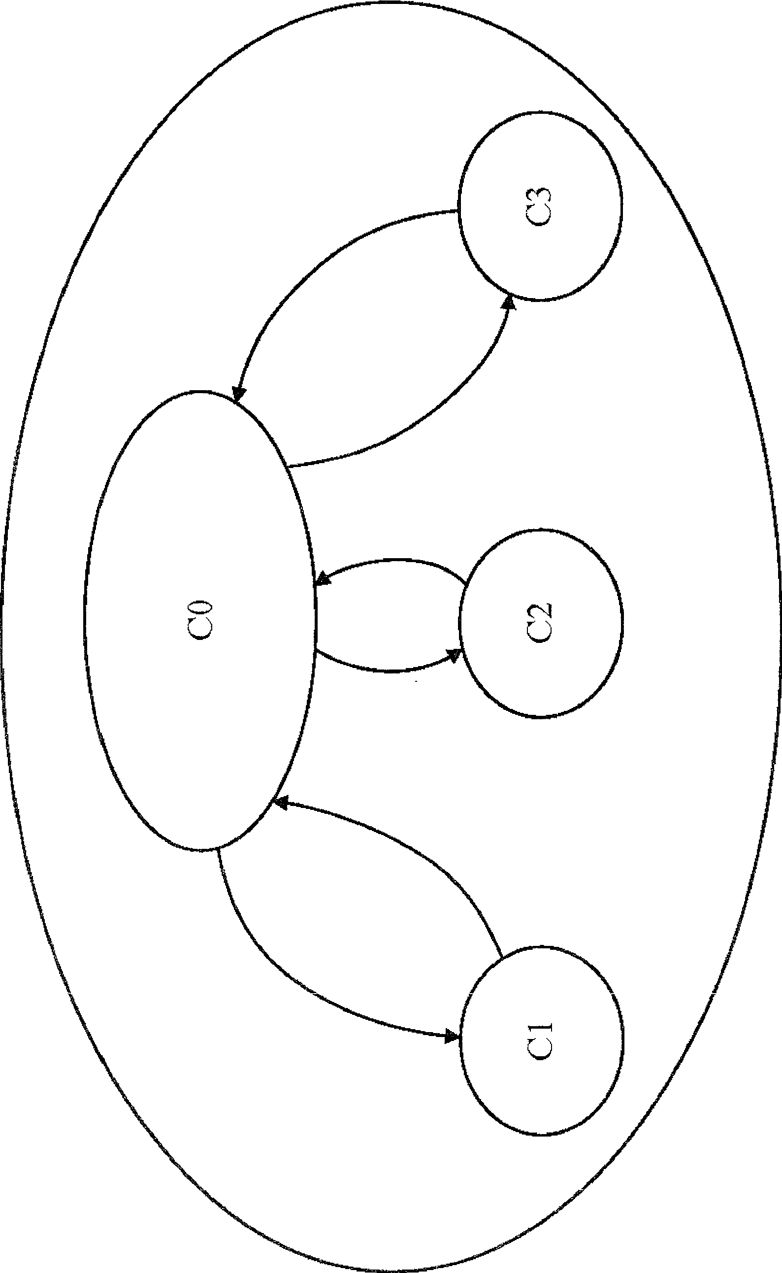
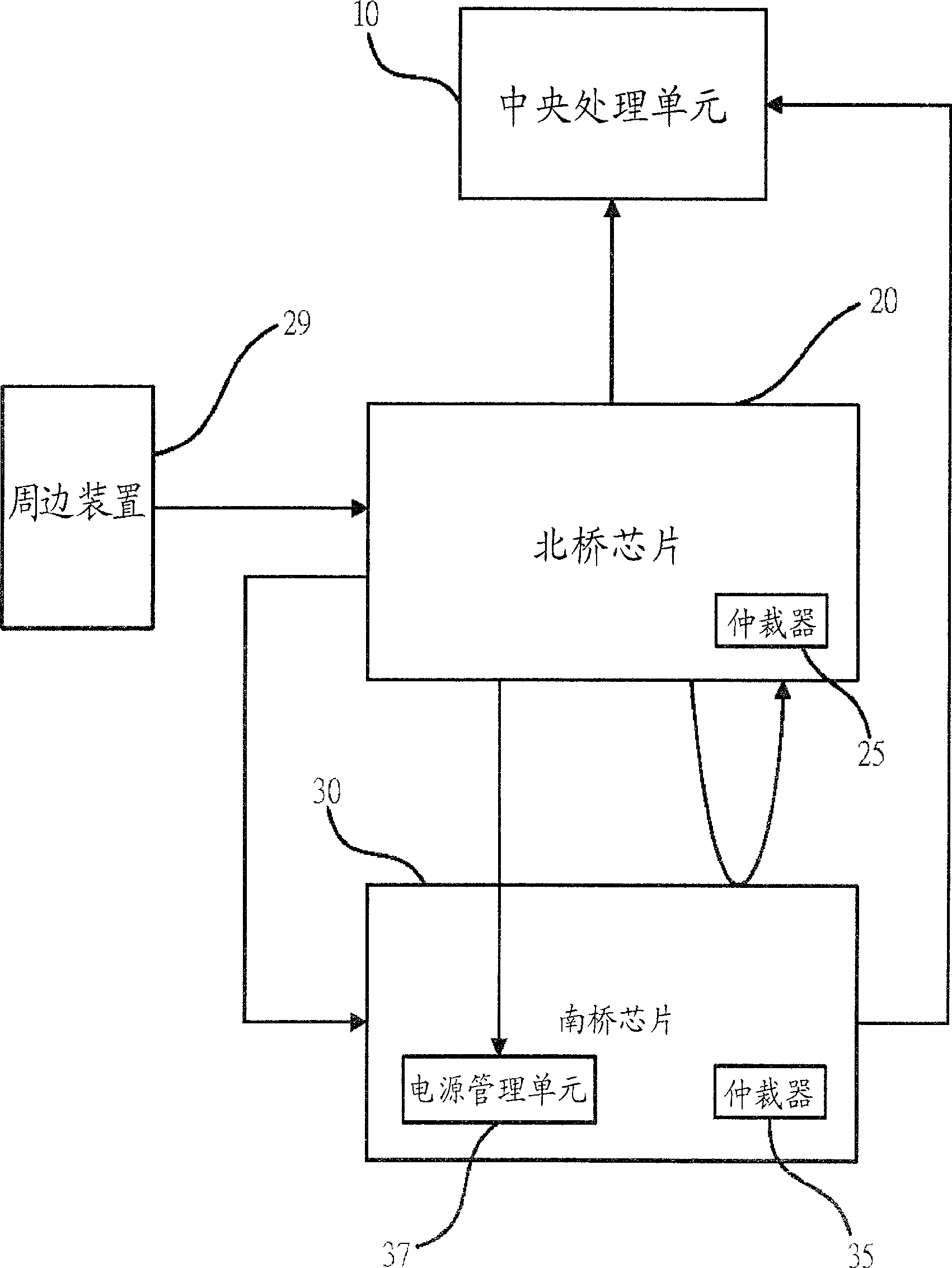
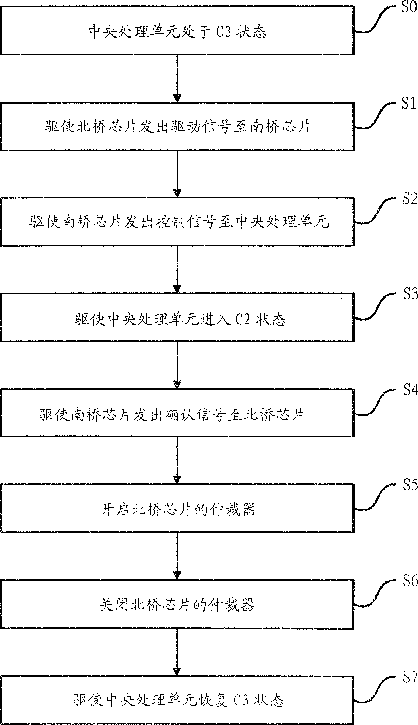
[0047] Please also see figure 2 and image 3 As shown, it is a block diagram and a flowchart of an embodiment of the present invention. As shown in step S0 , the central processing unit 10 is in the state C3 where events cannot be viewed, and the arbiter 25 of the north bridge chip 20 and the arbiter 35 of the south bridge chip 30 are both turned off. When the north bridge chip 20 receives the bus master signal sent by a peripheral device 29 connected, for example, when the high-speed graphics acceleration connection port (Accelerated Graphics Port, AGP) display card sends the bus master signal to the north bridge chip 20, the steps are executed S1,...


PUM


Abstract

This invention relates to one central process unit power management method, which is applied in central process unit in dormancy status on affairs cannot be spied; the north bridge chip or south one receive bus main control signals to send one control signals into central process unit to drive the central process unit into spying affair dormancy status; then the central process unit enters spying affairs dormancy status to drive south bridge chip to send sure signals into north bridge chip to supply for it to determine central process unit into spying affair dormancy; then driving the north bridge chip to start arbitrary device.

Description

technical field [0001] The present invention relates to a power management method, in particular to enable the central processing unit to enter the dormant state where the snoop event can be snooped when there is a bus master (Bus Master) signal. , a power management method for a central processing unit capable of data access. Background technique [0002] According to the current main power management systems of computer systems, there are two types: Advanced Power Management (APM) and Advanced Configuration and Power Interface (ACPI). APM is an early power management system with low performance. APM The biggest difference from ACPI is that APM performs power management through the basic input output system (BIOS) of the computer system, while ACPI performs power management through the operating system (Operating System, OS) of the computer system. The power management of ACPI is divided into four states, which are system state G (Global), device state D (Device), sleep st...

Claims


Application Information

Patent Timeline
Patent Type & Authority Patents(China)
IPC IPC(8): G06F1/32
Inventor 魏睿民黄正维苏耀群林瑞霖
Owner VIA TECH INC
Features
  • R&D
  • Intellectual Property
  • Life Sciences
  • Materials
  • Tech Scout
  • Unparalleled Data Quality
  • Higher Quality Content
  • 60% Fewer Hallucinations
Learn More