Single-brush two-phase 2/2 pole magnetoresistance vibrating electric machine

A brush and electrode technology, applied in circuits, current collectors, electrical components, etc., can solve the problems of high speed, lack of practical application value, uncertain direction of starting torque, etc., and achieve improved life, simple and reliable structure, and starting current. small effect

Inactive Publication Date: 2009-07-15
冯鲁民
View PDF4 Cites 0 Cited by
  • Summary
  • Abstract
  • Description
  • Claims
  • Application Information

AI Technical Summary

Problems solved by technology

Usually because the brush commutator of this kind of motor has no starting torque at a specific position of the rotor, the direction of the starting torque is uncertain, and there is a power short circuit at the moment of commutation, it lacks practical application value, but this kind of motor has a motor structure Simple, high torque and high speed characteristics

Method used


Image

  • Single-brush two-phase 2/2 pole magnetoresistance vibrating electric machine
  • Single-brush two-phase 2/2 pole magnetoresistance vibrating electric machine
  • Single-brush two-phase 2/2 pole magnetoresistance vibrating electric machine

Examples


Embodiment Construction

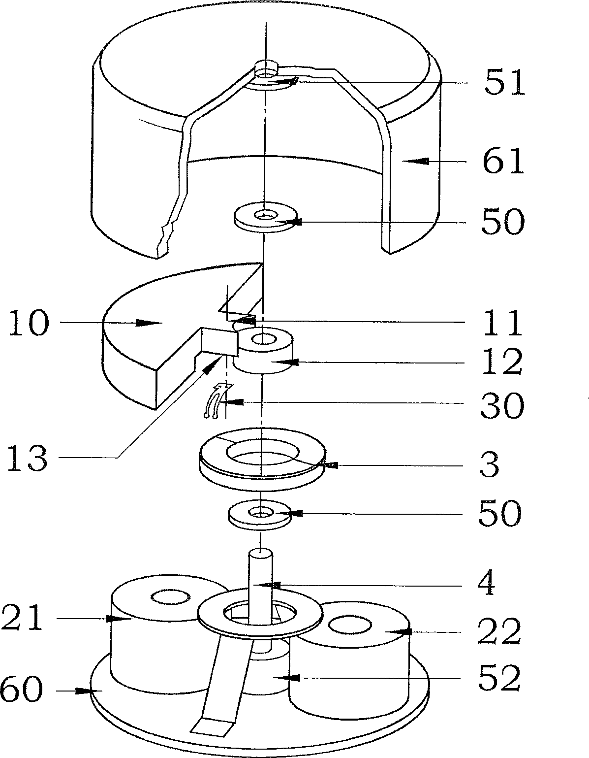
[0025] figure 1 Shown is a structural diagram of a DC miniature vibration motor according to the first preferred embodiment of the present invention. The motor adopts the stator coreless two-phase coils in series, and the rotor is in the form of two-pole eccentric permanent magnets.

[0026] The permanent magnet eccentric rotor (1) is located on the axial side of the stator coils 1 (21) and 2 (22), and is supported by the lower shaft seat (52) so that the rotor (1) and the stator coil (2) are in the axial direction. To maintain a very small magnetic air gap. The stator coils 1 (21) and 2 (22) are hollow, the axes of the two coils (21) and (22) are parallel to the fixed axis, and the line between the axes of the two stator coils is perpendicular to the axis of the fixed axis (4) . The stator coil 1 (21) and the stator coil 2 (22) are bonded and fixed on the motor bottom plate (60). One end of the fixed shaft (4) is fixed on the lower axle seat (52) of the motor base plate (...


PUM


Abstract

A structure of a two-phase 2/2-pole permanent magnet rotor DC vibration motor. One end of the coil in the stator is connected to the commutator piece, the other end is connected to one pole of the power supply, and the brush is connected to the other pole of the power supply; the rotor is composed of an eccentric permanent magnet and a shaft sleeve, and the stator is composed of coils arranged in line on both sides of the fixed shaft Composition, the rotor rotates on the fixed shaft with the help of the rotor sleeve; the fixed shaft neither coincides with the center of mass of the rotor, nor is it on the line of the rotor magnetic poles, thus forming an eccentric vibrator; the single brush commutator provides the starting torque and Stable running torque. After balancing the center of gravity of the rotor, the same motor structure can also be used for ordinary power motors; the same single-brush commutator can also be used for permanent magnet DC motors with armature rotors, and rotor position sensors that replace ordinary permanent magnet rotor DC motors , directly drive the high-power commutation circuit. The motor structure can also be applied to the multi-pole permanent magnet rotor DC motor.

Description

technical field [0001] The invention relates to the structure of a reluctance motor under an asymmetrical magnetic field, especially a flat miniature vibration motor. Background technique [0002] At present, there are two types of flat micro-vibration motor structures, one with a commutator and the other without a commutator, relying on an external commutation circuit to commutate the coil. [0003] Micro vibration motors are used in mobile phones or other personal portable electronic information products, and generally use batteries as power sources. Therefore, micro motors are required to consume less power on the one hand, small in size, and light in weight. On the other hand, they must meet the application purpose: Sufficient vibration force. At present, the vibration strength of the flat vibration motor with the coil as the rotor has basically reached the limit, and the complicated manufacturing process also makes it difficult to reduce the cost of the motor. [0004...

Claims


Application Information

Patent Timeline
Patent Type & Authority Patents(China)
IPC IPC(8): H02K13/04H01R39/04H02K7/065H02K23/00H02K23/04H02K7/06
CPCH02K7/063
Inventor 冯鲁民
Owner 冯鲁民
Why Eureka
Try Eureka