
Design method using double slit metallic structure to realize surface wave energy directional transmission

A metal structure, directional transmission technology, applied in optics, instruments, optical components, etc., can solve problems such as uncontrollable surface waves

Active Publication Date: 2009-07-22
INST OF OPTICS & ELECTRONICS - CHINESE ACAD OF SCI
View PDF3 Cites 0 Cited by
  • Summary
  • Abstract
  • Description
  • Claims
  • Application Information

AI Technical Summary

Problems solved by technology

[0004] The technical problem to be solved by the present invention is: aiming at the uncontrollable problem of the surface wave excited by the existing metal grating structure, a metal grating structure that can control the excitation direction of the surface wave is proposed

Method used


Image

  • Design method using double slit metallic structure to realize surface wave energy directional transmission
  • Design method using double slit metallic structure to realize surface wave energy directional transmission
  • Design method using double slit metallic structure to realize surface wave energy directional transmission

Examples


Embodiment Construction

[0036] The present invention will be described in detail below in conjunction with the accompanying drawings and specific embodiments, but the scope of protection of the present invention is not limited to the following embodiments, but should include all content in the claims; All the contents in the claims are realized.

[0037] The concrete steps of the embodiment of the present invention are as follows:

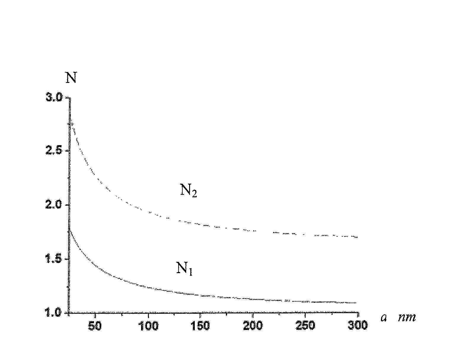
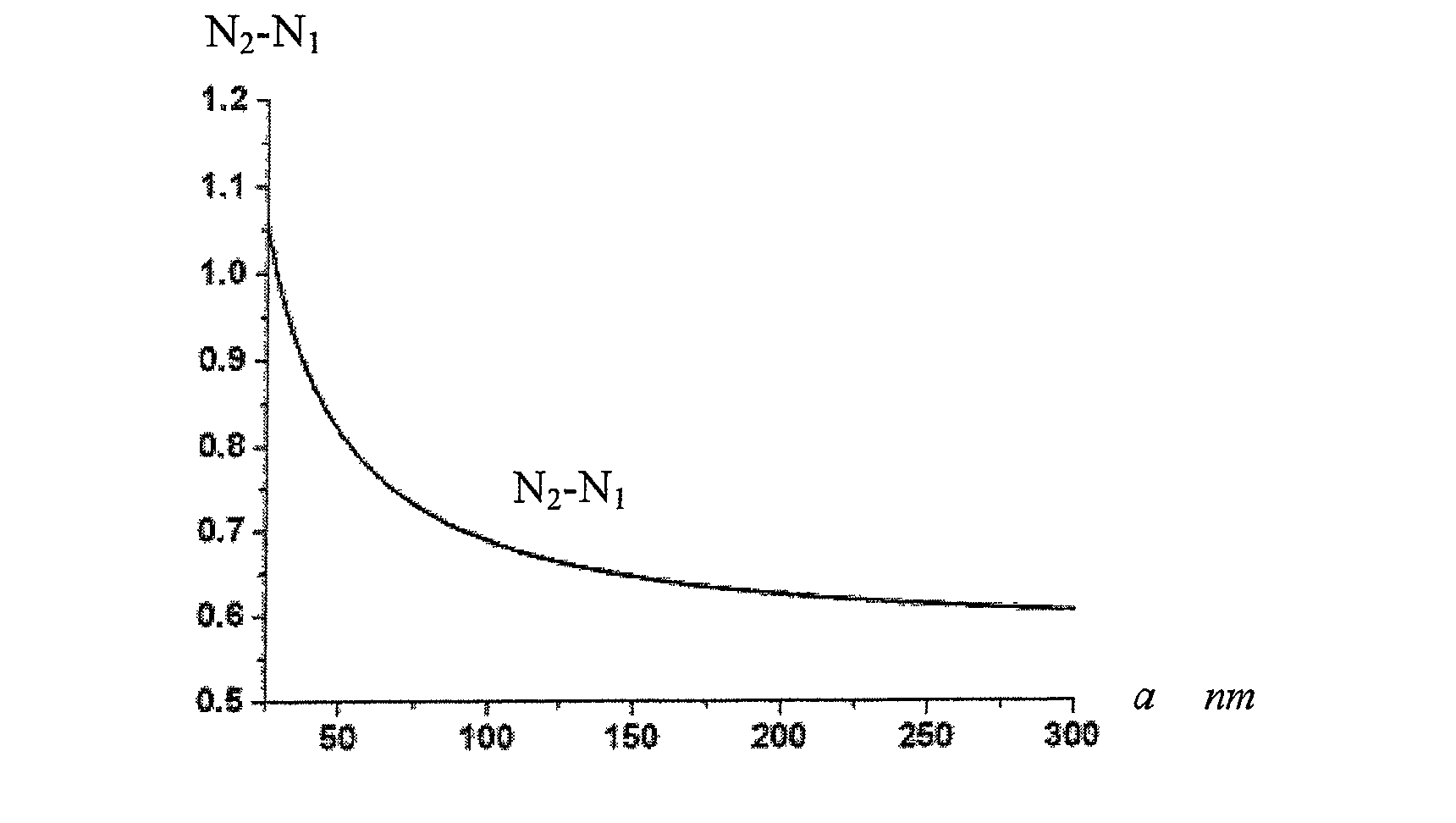
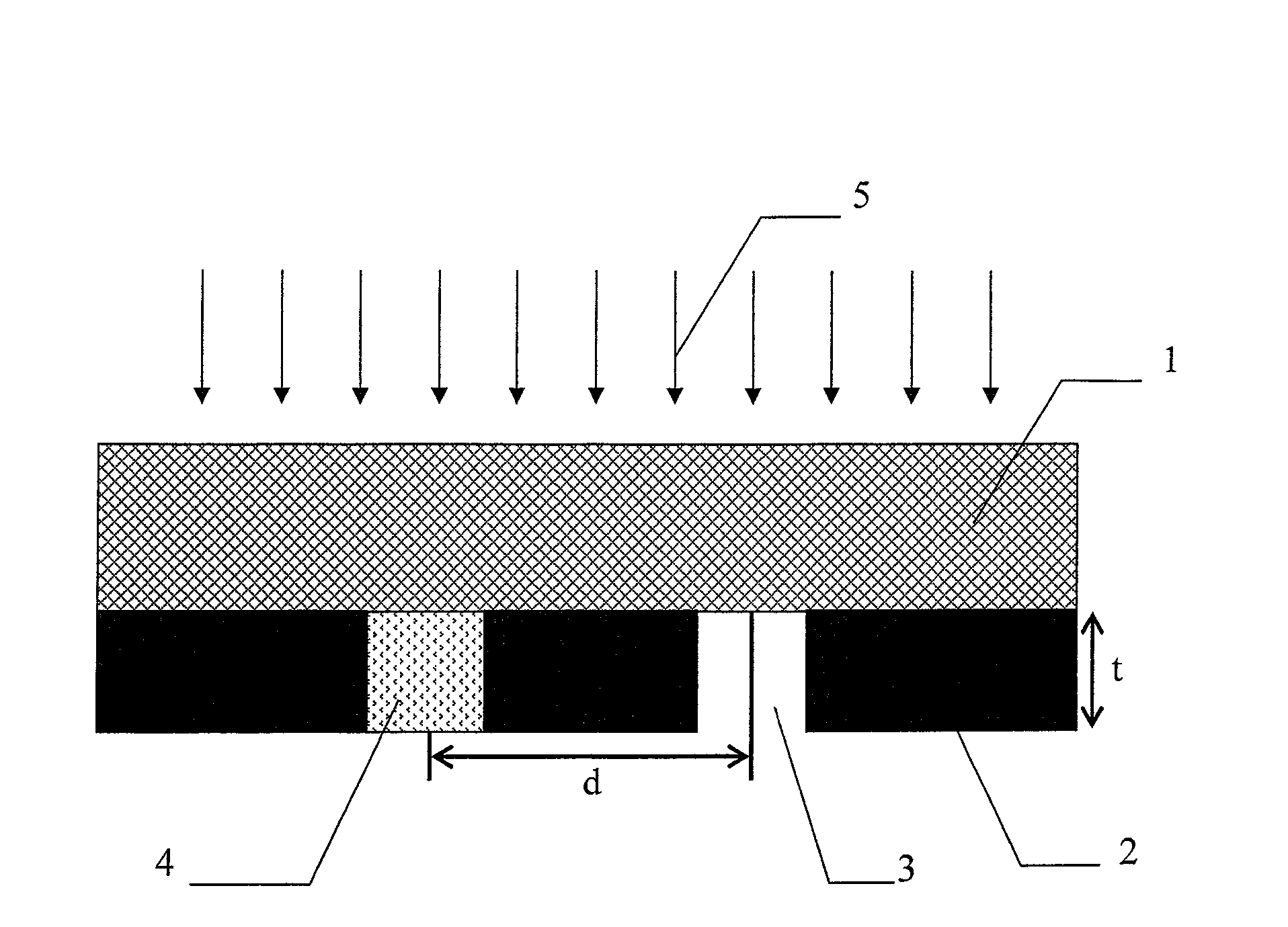
[0038] (1) Determine the incident wavelength λ to be 632.8nm, choose silica S i o 2 The material is used as a substrate, and a 200nm metal silver layer is evaporated on its surface, that is, t=200mm;

[0039] (2) Open two slit structures with a width a on the silver layer, and the distance between the centers of the two slits is d;

[0040] (3) Choose air and n 2 The dielectric material of =1.52 fills two metal slits respectively, and the refractive index n of air 1 = 1, the incident light is incident perpendicular to the other surface of the substrate, assuming that...


PUM


Abstract

The design method of realizing the directional transmission of surface wave energy by using a double-slit metal structure is characterized in that: determine the incident light, select the substrate according to its wavelength λ, and vapor-deposit a metal layer with a thickness t on its surface; open two slits on the metal layer , assuming that the slit width is a, the distance between the centers of the two slits is d, and two different media are filled respectively; let the incident light be incident on the other surface of the substrate, we can know the equivalent refractive index of the two media under the action of the incident light, by modulating the two metal slits The initial phase of the surface wave excited at the exit makes the propagation direction of the outgoing light field in a specific direction, through the relationship between the width of the slit and the equivalent refractive index of the medium in the slit and the surface excited at the exit of the two metal slits The wave initial phase formula can be calculated to obtain the designed metal slit width a and the distance between two slit centers d; the structure designed by the present invention is simple, and the design and manufacture of the entire structure can be completed on one metal surface, and the structure can be used for In devices that require directional coupling, directional control of the beam is achieved.

Description

technical field [0001] The invention relates to a design method for a micro-nano structure, in particular to a design method for realizing directional transmission of surface wave energy by using a double-slit metal structure. Background technique [0002] In recent years, with the rapid development of micro-nano processing technology and nanomaterials, the electromagnetic properties of micro-nano metal structures are receiving more and more attention. The interaction of light with surface micro-nano metal structures produces a series of new and exotic physical phenomena. For example, in 1998, French scientist Ebbesen and his collaborators discovered the phenomenon of extraordinary enhancement (Extraordinary Optical Transmission) of light passing through a subwavelength metal hole array. The research of H.J.Lezec et al. further showed that: when the light passes through the sub-wavelength metal nanohole, its transmittance can not only be enhanced, but also the diffraction a...

Claims


Application Information

Patent Timeline
Patent Type & Authority Patents(China)
IPC IPC(8): G02B27/00G02B5/18
Inventor 罗先刚徐挺杜春雷王长涛
Owner INST OF OPTICS & ELECTRONICS - CHINESE ACAD OF SCI
Learn More