Flexible connecting line structure between integrated circuit board in the finger of robot delicacy hand

A technology of integrated circuit boards and circuit boards, which is applied in the direction of cable layout between relative moving parts, manipulators, cable installation, etc., and can solve problems such as poor adaptability of rotating joints, unreasonable layout of circuit boards, and unreasonable wiring methods , to achieve the effect of reasonable routing, avoiding signal interference, and good adaptability

Inactive Publication Date: 2009-08-05
HARBIN INST OF TECH
View PDF4 Cites 0 Cited by
  • Summary
  • Abstract
  • Description
  • Claims
  • Application Information

AI Technical Summary

Problems solved by technology

[0004] The present invention solves the problems of unreasonable circuit board layout, complex wiring, unreasonable routing and poor reliability in the circuit board and its connection arrangement in the existing robot dexterous hand fingers, so that it is difficult to realize electromechanical integration and finger connection. Poor adaptability to rotating joints and problems affecting the movement of joints, and then provides a flexible connection structure between integrated circuit boards in the fingers of robotic dexterous hands

Method used


Image

  • Flexible connecting line structure between integrated circuit board in the finger of robot delicacy hand
  • Flexible connecting line structure between integrated circuit board in the finger of robot delicacy hand
  • Flexible connecting line structure between integrated circuit board in the finger of robot delicacy hand

Examples


specific Embodiment approach 1

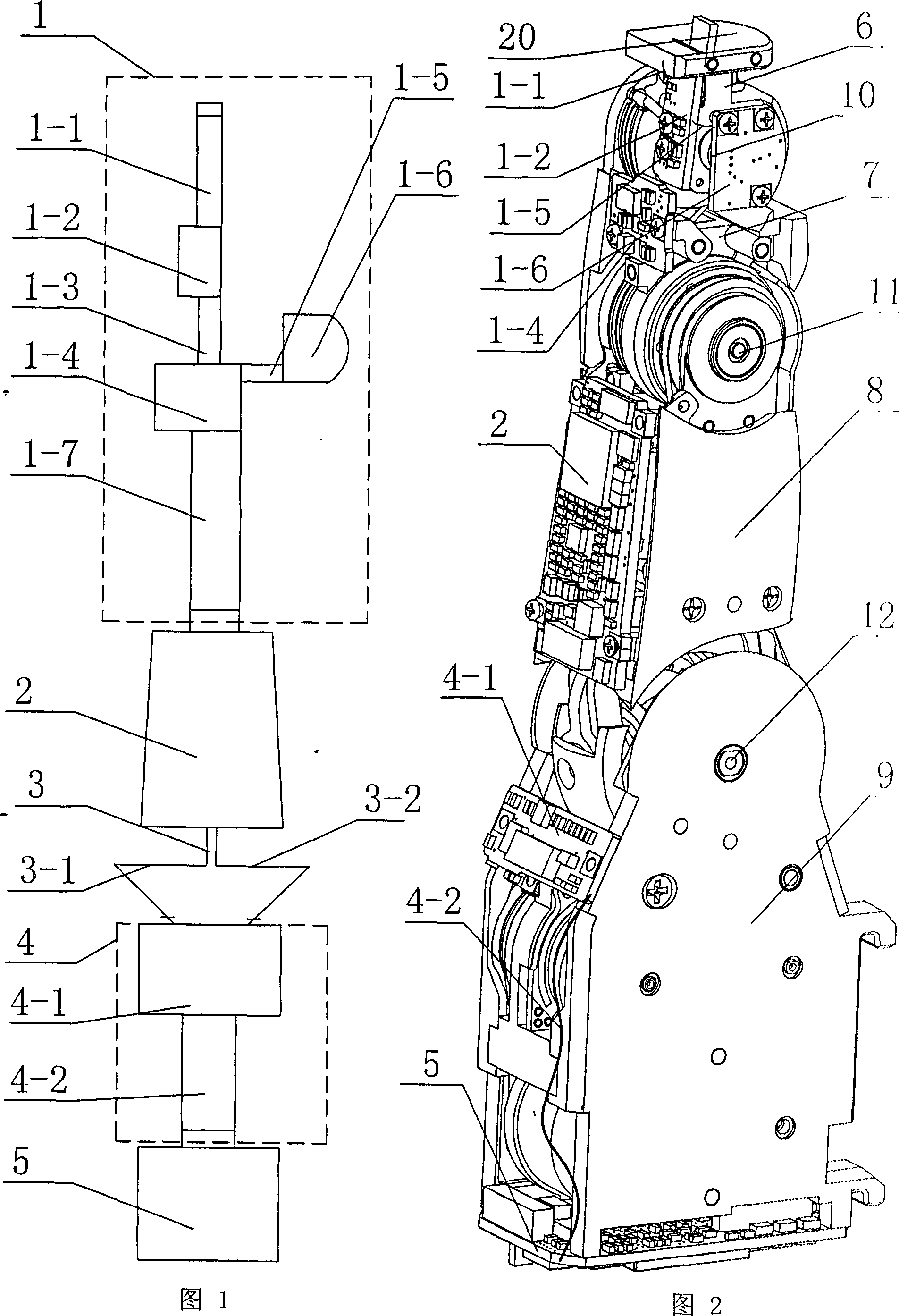
[0008] Embodiment 1: As shown in Figures 1 to 9, the flexible connection structure between the integrated circuit boards in the fingers of the robotic dexterous hand in this embodiment consists of a finger flexible circuit board 1, a finger rigid circuit board 2, and a base joint flexible connection harness 3. The base joint flexible circuit board 4 and the base joint rigid circuit board 5 are composed; the finger flexible circuit board 1 is composed of a first rigid board 1-2, a second rigid board 1-4, a third rigid board 1-6, The first flexible cable 1-1, the second flexible cable 1-3, the third flexible cable 1-5, and the fourth flexible cable 1-7, the first rigid plate 1-2 is fixed on the terminal knuckle 6 Above, the second rigid board 1-4 and the third rigid board 1-6 are respectively fixed on the second knuckle 7 and are perpendicular to each other, one end of the first flexible cable 1-1 is connected to the fingertip torque sensor 20, the first The other end of the fle...

specific Embodiment approach 2

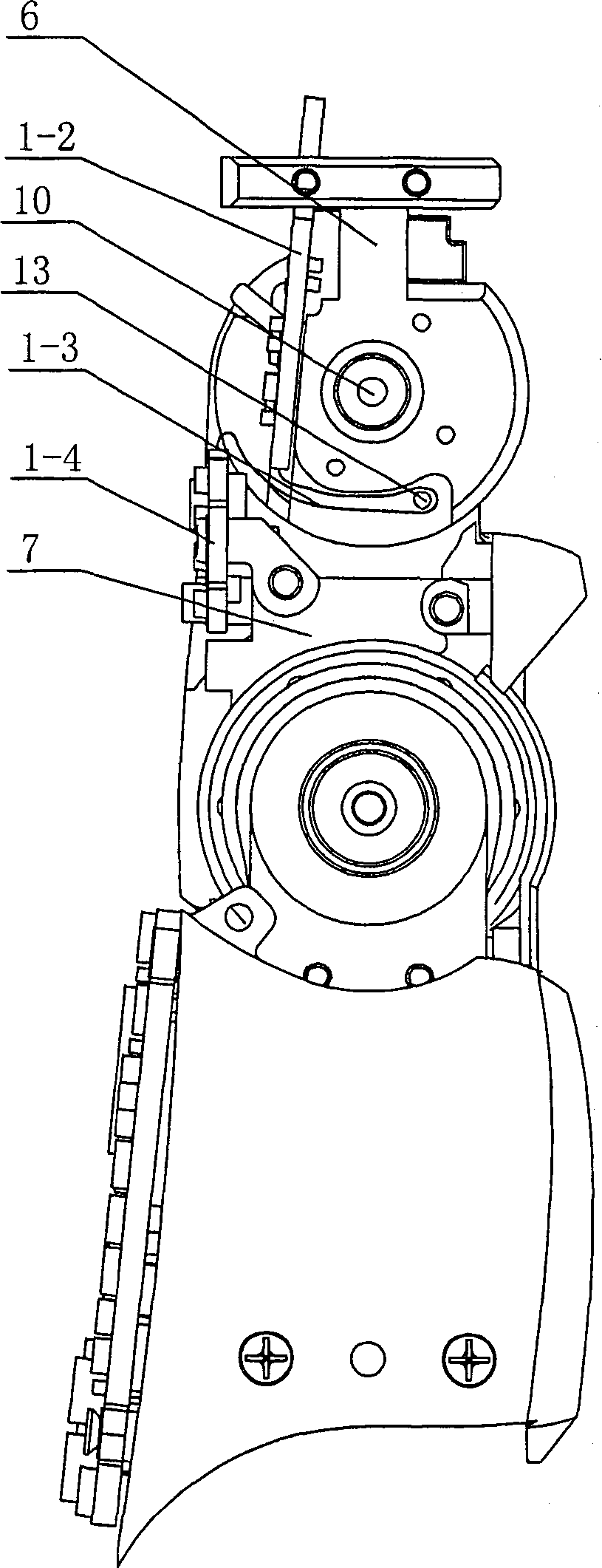
[0009] Specific implementation mode two: as image 3 and Figure 4 As shown, this embodiment further includes a wire pin 13 , the wire pin 13 is arranged on the terminal knuckle 6 , and the second flexible cable 1 - 3 is wound on the wire pin 13 . When the finger end joints are straightened, the distance between the first rigid plate 1-2 and the second rigid plate 1-4 is the smallest, and the excessively long second flexible cable 1-3 is affected by the guide pin 13 and its own rigidity down, folded on the inner side of the second knuckle 7; when the end joint 10 gradually bends, the distance between the first rigid board 1-2 and the second rigid board 1-4 increases, and the second flexible cable 1 is pulled -3, at the same time, the wire pin 13 rotates clockwise around the end joint 10, and the second flexible cable 1-3 can meet the requirement of increasing the distance between the two rigid plates. The function of the wire pin 13 is mainly to pull up the second flexible c...

specific Embodiment approach 3

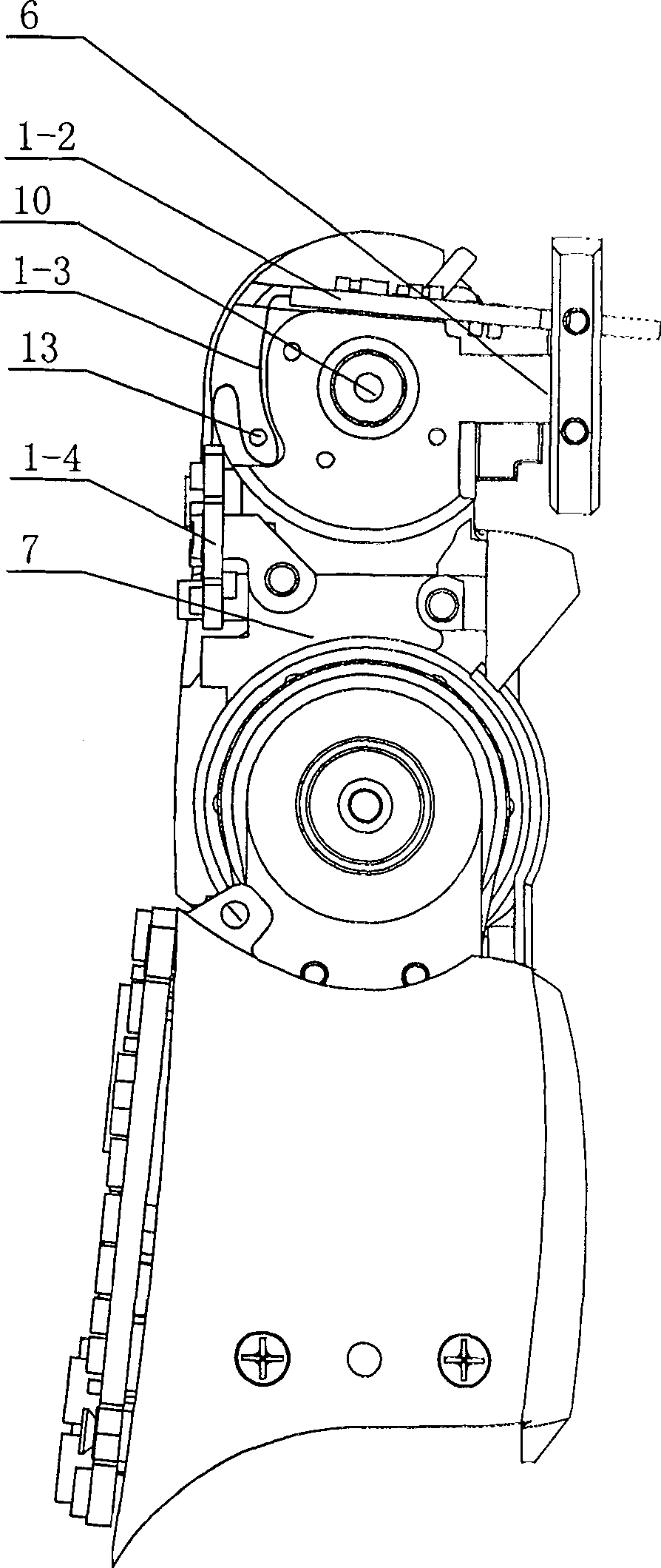
[0010] Specific implementation mode three: as Figure 5 and Figure 6 As shown, the fourth flexible cable 1-7 in this embodiment spans the middle joint 11, the second rigid board 1-4 and the finger rigid circuit board 2. When the middle joint 11 is straightened, the distance between the second rigid board 1-4 and the finger rigid circuit board 2 is the smallest, and the excessively long fourth flexible cable 1-7 winds around the middle joint 11 under the action of its own stiffness the inner side of the second knuckle 7; when the second knuckle 7 of the finger is gradually bent, the distance between the two rigid plates increases, pulling the fourth flexible cable 1-7, and the fourth flexible cable 1-7 can meet the requirement of increased rigid board distance. Other compositions and connections are the same as in the first embodiment.


PUM


Abstract

The invention relates to a flexible connection structure between integrated circuit boards in the fingers of a robot dexterous hand, which relates to a connection structure between integrated circuit boards in the fingers of a robot. The invention solves the problems of unreasonable circuit board layout, complicated connection and unreasonable wiring mode existing in the prior art. One end of the second flexible cable (1-3) is connected to the first rigid board (1-2), the other end is connected to the second rigid board (1-4), and one end of the fourth flexible cable (1-7) Connect with the second rigid board (1-4); the other end of the fourth flexible cable (1-7) is connected with the finger rigid circuit board (2), and one end of the base joint flexible connection harness (3) is connected with the finger rigid circuit board (2) connection, the other end is connected to the fourth rigid board (4-1); one end of the fifth flexible cable (4-2) is connected to the fourth rigid board (4-1), and the other end is connected to the base joint rigid circuit Plate (5) is connected. The invention has the advantages of reasonable circuit board layout, reasonable routing mode, no influence on the movement of joints, and good adaptability of finger connecting lines to rotating joints.

Description

technical field [0001] The invention relates to a wiring structure between integrated circuit boards in a robot finger. Background technique [0002] As the end effector of the robot system, the robotic dexterous hand has an important impact on the operation ability of the robot system, especially the dexterous operation ability. After the 1980s, some countries carried out research on robotic dexterous hands, and some representative dexterous hands were born one after another, such as Stanford / JPL hand, Utan / M.I.T hand, DLR hand, NASA hand, etc. The concept, drive, sensor and other aspects of the dexterous hand have had a great impact on the follow-up and even today's research on dexterous hands. As one of the important components of the robot dexterous hand, the electrical system mainly realizes functions such as motor drive and sensor information collection. have an important impact. Built-in and external are the two main research directions in the current dexterous han...

Claims


Application Information

Patent Timeline
Patent Type & Authority Patents(China)
IPC IPC(8): B25J15/00B25J17/00H05K7/02H02G11/00
Inventor 刘宏刘伊威陈兆芃金明河樊绍巍姜力
Owner HARBIN INST OF TECH
Why Eureka
Try Eureka