
Vacuum compression bag gas nozzle with improved structure

A technology of vacuum compression bags and air nozzles, which is applied in the direction of ventilation devices, mechanical equipment, etc., which can solve the problems of inconvenient operation, easy gaps, and low sealing performance, and achieve good gas fluidity, easy operation and assembly, and tightness Good results

Inactive Publication Date: 2009-08-05
梁灼权
View PDF7 Cites 0 Cited by
  • Summary
  • Abstract
  • Description
  • Claims
  • Application Information

AI Technical Summary

Problems solved by technology

But the air nozzle of the vacuum compression bag of this structure still has the following deficiencies: (1), the air extraction hole on the air nozzle body is mainly sealed by a movable film, and the movable film is arranged on the air extraction hole by utilizing the pressure difference between the inside and outside of the bag. On the other hand, if the bag body after vacuuming encounters a large external force of vibration, there is likely to be a gap between the movable film and the air hole, which will cause the bag body to leak air. Therefore, its sealing performance is poor, resulting in waterproof, mildew-proof and moisture-proof effects. Poor; (2) When pumping air, the gas in the bag is mainly drawn out through the suction hole by the force of the suction pump. The force of the gas on the side of the gas nozzle body suction hole is small; that is, when the gas nozzle body of this structure pumps air to the bag body, the gas pumping is uneven and the gas fluidity is poor, resulting in unsatisfactory pumping effect and affecting the preservation of clothes. (3), the soft plug setting on the gas nozzle body, except that the sealing performance is relatively low, its operation is also inconvenient; moreover, the soft plug is used for a long time, and it is easy to deposit between the soft plug mouth of the gas nozzle body and the soft plug. There is a gap

Method used


Image

  • Vacuum compression bag gas nozzle with improved structure
  • Vacuum compression bag gas nozzle with improved structure
  • Vacuum compression bag gas nozzle with improved structure

Examples


Embodiment Construction

[0016] The present invention will be further described below in conjunction with the accompanying drawings and embodiments.

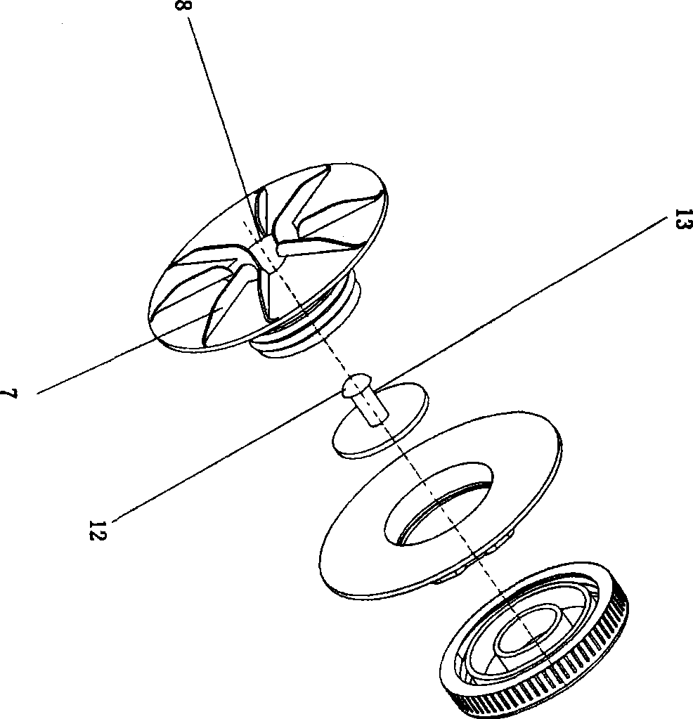
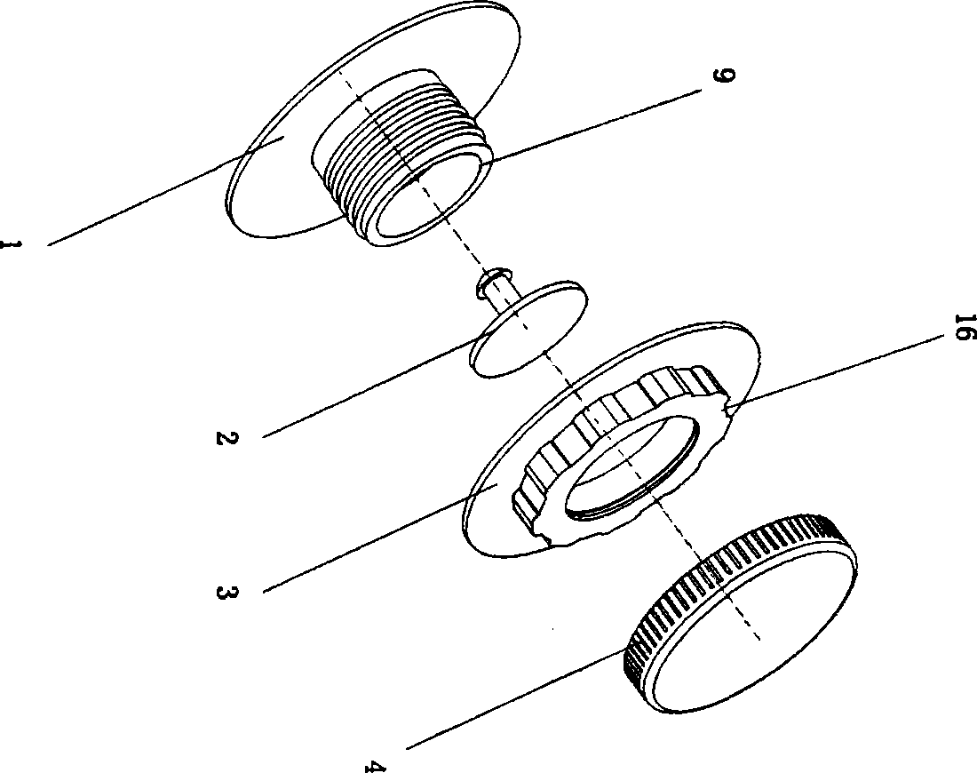
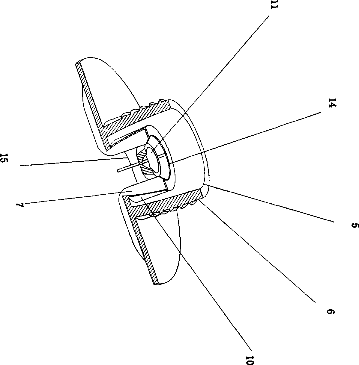
[0017] refer to Figure 1 to Figure 3 As shown, a vacuum compression bag nozzle with an improved structure includes a seat body 1, a sealing ring 3 and an end cover 4, the seat body 1 has an air inlet 8 and an air outlet 9, and the air outlet 9 of the seat body 1 is respectively screwed with The sealing ring 3 and the end cap 4, the top of the sealing ring 3 is provided with a convex handle 16, the seat body 1 is composed of an inner sleeve 5 and an outer sleeve 6, and the upper part of the inner sleeve 5 and the outer sleeve 6 is a circular boss, the The outer wall of the circular boss on the upper part of the jacket 6 is provided with an external thread, the sealing ring 3 and the end cap 4 are screwed on the outer wall of the circular boss, the inner jacket 5 has an exhaust passage 10, and the exhaust passage 10 of the inner jacket 5 enters the air ...


PUM


Abstract

An air nozzle for a vacuum compression bag with an improved structure, including a seat body, a sealing ring and an end cover, the seat body has an air inlet and an air outlet, and the air outlet of the seat body is respectively screwed with a sealing ring and an end cover. The base body is composed of an inner sleeve and an outer sleeve. The inner sleeve has an exhaust channel. The air inlet end of the exhaust channel of the inner sleeve extends out of the bottom of the outer sleeve and forms the air inlet of the base body. The air outlet of the base body is located at the top opening of the outer sleeve. The inner wall of the exhaust passage is provided with a deflector, and the deflector extends out of the air inlet end of the exhaust passage. A circular ring is also fixed in the exhaust passage, and a piston pad is provided at the outlet end of the exhaust passage of the inner sleeve, and a There is an inserting shaft with a chuck, and the chuck on the inserting shaft passes through the ring and is clamped outside the ring, and the piston pad is placed on the upper part of the inner sleeve and seals the outlet end of the exhaust passage. The beneficial effect of the present invention is that such a structure has good airtightness, and there is sufficient space for the gas to flow during pumping, and the pumping effect is ideal.

Description

technical field [0001] The invention relates to an air nozzle for a vacuum compression bag, in particular to an air nozzle for a vacuum compression bag with an improved structure to improve the suction effect and sealing performance of the bag body. Background technique [0002] For areas with rainy seasons, the problem of storing heavy clothes and quilts has always troubled people. Vacuum compression bags are widely used because of their protective functions such as waterproof, mildew-proof, and moisture-proof; their structure is as follows: 200520005269.5; the name is "Vacuum Compression Bag Air Nozzle", authorized announcement date: April 5, 2006; the vacuum compression bag air nozzle includes a valve body and a soft plug. There are raised columns on the body, and the columns are distributed around the air extraction holes. There is also a movable film on the outside of the valve body. The collar on one side hangs on the valve body. When using, first pull out the soft p...

Claims


Application Information

Patent Timeline
Patent Type & Authority Patents(China)
IPC IPC(8): F16K24/00
Inventor 梁灼权
Owner 梁灼权
Learn More