
A baffle and a vacuum dryer comprising the baffle

A baffle and panel technology, which is applied in the field of liquid crystal display panel manufacturing, can solve the problems of poor air extraction at the center and uneven air extraction of the array substrate, and achieve the effects of uniform air extraction, avoiding poor air extraction and uniform airflow.

Active Publication Date: 2019-09-17
WUHAN CHINA STAR OPTOELECTRONICS TECH CO LTD
View PDF3 Cites 0 Cited by
  • Summary
  • Abstract
  • Description
  • Claims
  • Application Information

AI Technical Summary

Problems solved by technology

[0005] In order to solve the problem of poor pumping at the center caused by the uneven pumping of the array substrate caused by the baffle in the prior art, the present invention proposes a baffle, and further proposes a vacuum dryer including the baffle

Method used


Image

  • A baffle and a vacuum dryer comprising the baffle
  • A baffle and a vacuum dryer comprising the baffle
  • A baffle and a vacuum dryer comprising the baffle

Examples


Embodiment 1

[0032] Such as Figure 5 Is a schematic diagram of the first baffle 23 proposed by the present invention, Image 6 for Figure 5 A-A section view, combined Figure 5 with Image 6 The baffle 23 includes a first plate surface 233 and a second plate surface 234. The first plate surface 233 and the second plate surface 234 are arranged relatively parallel, and the first plate surface 233 and the second plate surface 234 are respectively arranged on the baffle plate 23. Viewed along the normal direction of the first plate surface, the central area of ​​the baffle 23 has a hole 232 passing through the first plate surface 233 and the second plate surface 234, such as Figure 5 As shown, the hole 232 passes through the first panel surface 233 and the second panel 234, wherein the size of the hole 232 can be adjusted according to actual conditions.

[0033] When the hole 232 is provided at the center of the baffle 23, the volatilized gas in the central area of ​​the array substrate can dir...

Embodiment 2

[0038] In the second embodiment of the present invention, different from the first embodiment, the cross-sectional view of the baffle 23' along A-A is as Figure 7 As shown, the cross section of the peripheral surface 2321' of the hole 232' of the baffle 23' gradually decreases from the second plate surface 234' to the first plate surface 233' along the normal direction of the first plate surface. The angle β between the surface 2321' and the first plate surface 233' is 30 degrees. At the same time, the peripheral surface 237' of the baffle 23' is no longer perpendicular to the first plate surface 233', but the outer peripheral surface of the baffle 23' 237' gradually increases from the second board surface to the first board surface along the normal direction of the first board surface, such as Figure 7 As shown, preferably, the included angle θ between the circumferential surface 237' of the baffle 23' and the first plate surface 233' is 30 degrees.

[0039] When the circumfere...


PUM


Abstract

The invention relates to the technical field of liquid crystal display panel manufacturing, and provides a blocking plate. The blocking plate comprises a first plate face and a second plate face, wherein the first plate face and the second plate face are parallel to each other, the first plate face and the second plate face are arranged at the two sides of the blocking plate respectively, observed from the normal direction of the first plate face, the central area of the blocking plate is provided with a hole, the hole penetrates through the first plate face and the second plate face of the blocking plate, in a vacuum drier, the blocking plate is put above an array substrate to be dried, an exhaust air duct can conduct air exhaust drying on the array substrate directly from the central part of the blocking plate so as to make the airflow path in the central area of the array substrate shorten, the air exhaust effect in the central area of the array substrate is improved, thus the airflow above the array substrate is more even, a central defect caused by unevenness of the air exhaust is avoided, and the quality of a product is improved. The invention provides the vacuum drier comprising the blocking plate at the same time.

Description

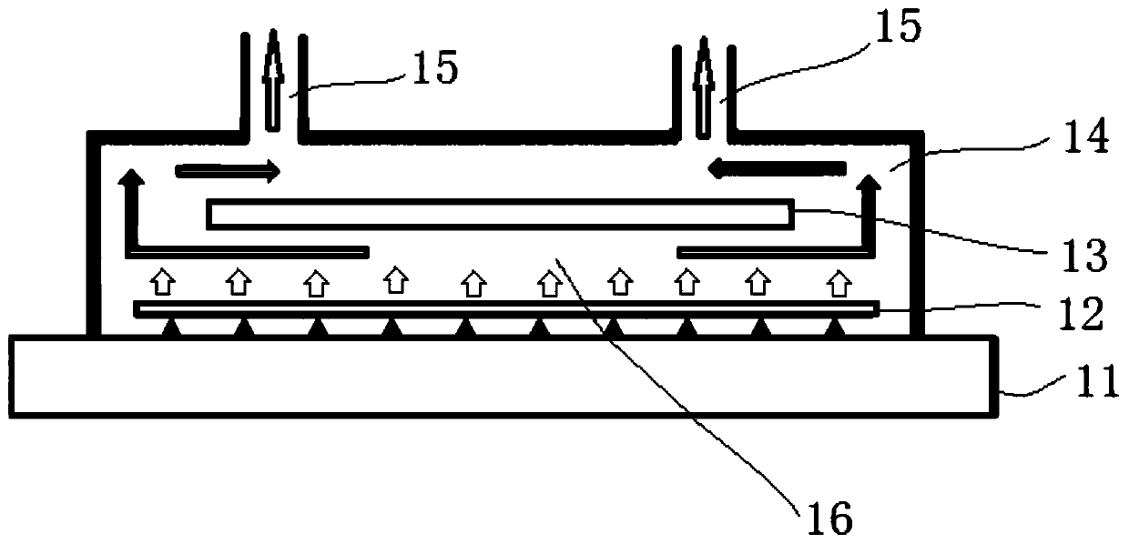
Technical field [0001] The present invention relates to the technical field of liquid crystal display panel manufacturing, in particular to a baffle and a vacuum dryer including the baffle. The baffle is arranged in an air chamber of the vacuum dryer and located between a substrate to be dried and an exhaust pipe . Background technique [0002] Photoresist, also known as photoresist, is a light-sensitive mixed liquid composed of three main components: photosensitive resin, sensitizer and solvent. The solvent is mainly organic solvent. After the photosensitive resin is exposed to light, The area can quickly undergo light curing reaction, which makes the physical properties of this material, especially solubility, affinity, etc., undergo significant changes. After proper solvent treatment, the soluble part is dissolved to obtain the desired image. [0003] In the manufacturing technology of liquid crystal display panels, in the manufacturing process of the array substrate, in the ph...

Claims


Application Information

Patent Timeline
Patent Type & Authority Patents(China)
IPC IPC(8): G02F1/13G03F7/40
Inventor 许可徐彬
Owner WUHAN CHINA STAR OPTOELECTRONICS TECH CO LTD
Learn More