Supercharge Your Innovation With Domain-Expert AI Agents!

Optical apparatus for fluorescence observation

An optical device and fluorescence technology, applied in optics, optical components, measuring devices, etc., can solve the problems of material considerations without optical performance, optical deformation, difficult bonding, etc., and achieve the effect of good transparency and high contrast

Inactive Publication Date: 2009-08-12
OLYMPUS CORP
View PDF7 Cites 0 Cited by
  • Summary
  • Abstract
  • Description
  • Claims
  • Application Information

AI Technical Summary

Problems solved by technology

[0009] However, the technology described in Japanese Patent Application Laid-Open No. 2000-284181 only focuses on the lenses constituting the optical system, and does not consider any other materials with optical properties.
In addition, the objective lens disclosed in Japanese Patent Application Laid-Open No. 11-23976 has a structure that does not use an adhesive, but if an adhesive is not used, it is very difficult to bond materials with curvature, and there is a combination of lenses with different shapes. Problems where structures are prone to optical distortion due to temperature changes
[0010] In addition, in the fluorescence endoscope device described in Japanese Patent Application Laid-Open No. 2002-10969, the reflected excitation light can be removed by the excitation light cut filter, but the autofluorescence generated by the materials constituting the optical system cannot be removed, so it cannot Solve the problem of contrast drop

Method used


Image

  • Optical apparatus for fluorescence observation
  • Optical apparatus for fluorescence observation
  • Optical apparatus for fluorescence observation

Examples


Embodiment 1

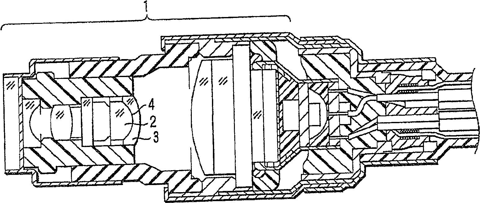
[0042] figure 2 It is a sectional view showing the tip of an insertion portion of an endoscope according to an embodiment of the present invention. exist figure 2 The distal end of the insertion portion of the shown endoscope has an observation objective optical system 1 including a plurality of lenses built into the distal end body, including the adhesive (silicone adhesive) 4 of the first embodiment described above. A cemented lens made by cementing lens 2 and lens 3 together.

[0043] That is, apply a small amount of silicone adhesive 4 on the bonding surface of lens 3, and after bonding lens 2 and lens 3, spread silicone adhesive 4 to the entire bonding surface, leave it at room temperature or heat to cure, Thus, a cemented lens is produced.

[0044] In this embodiment, the base resin of the silicone adhesive 4 is in contact with the platinum group metal catalyst, so that the silicone adhesive is cured, and the lens 2 and the lens 3 are fixed. In this case, the occur...

Embodiment 2

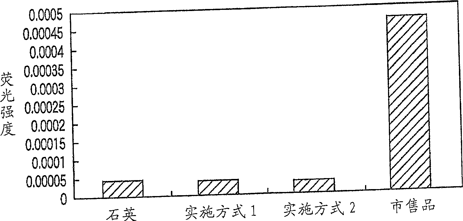
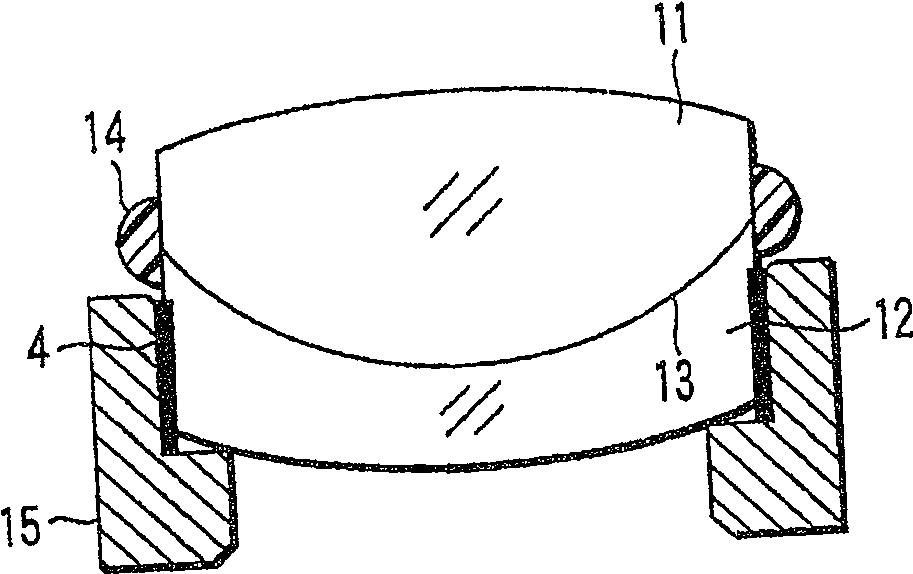
[0048] image 3 Representative cemented lenses of microscope objectives for fluorescence observation are shown. The first lens 11 and the second lens 12 are bonded with the silicone oil 13 of the above-mentioned second embodiment, and a sealant 14 is formed on the outer periphery of the adjacent edge portion of the first lens 11 and the second lens 12. The gaps of the mirror frame 15 are filled with the silicone adhesive 4 according to Embodiment 1 for bonding and fixing.

[0049] In the silicone adhesive 4 and the silicone oil 13 used in this example, the impurity content of platinum group metal catalysts, multiple bonding groups, transition metals, and rare earth elements is reduced, so that the generation of autofluorescence can be suppressed to a minimum. lower.

[0050] In particular, by making the silicone oil 13 completely free of platinum group metal catalysts, and making multiple bonding groups (phenyl, carboxyl, sulfinyl, ether, acryloyl, acetyl, etc.) and transiti...


PUM


Abstract

The present invention provides an optical device for fluorescence observation, the optical device for fluorescence observation has a plurality of optical elements, and the optical device for fluorescence observation is characterized in that a silicone adhesive is present between the plurality of optical elements In order to join the two, the silicone-based adhesive contains a substance with low autofluorescence.

Description

technical field [0001] The present invention relates to an optical device for fluorescence observation, and more particularly to an optical device for fluorescence observation such as a microscope for fluorescence observation and an endoscope that irradiates an object to be observed with ultraviolet excitation light to observe the object for fluorescence. Background technique [0002] In recent years, in the field of biological observation of cells, genes, etc., fluorescence observation using a fluorescence microscope, a fluorescence endoscope, etc. to capture weak fluorescence (autofluorescence) generated when a living body is irradiated with excitation light has become mainstream. Since it can be observed without damaging cells by fluorescently staining a specific substance, in this observation, short-wavelength light is directly irradiated to the specimen or cells in the body, and the resulting fluorescence is observed. [0003] For example, in a fluorescence microscope, ...

Claims


Application Information

Patent Timeline
Patent Type & Authority Patents(China)
IPC IPC(8): G02B21/00
CPCG02B13/143G02B1/00C03C27/10G01N21/6486G01N21/6458G02B23/243G02B21/16
Inventor 林孝枝木下博章
Owner OLYMPUS CORP
Features
  • R&D
  • Intellectual Property
  • Life Sciences
  • Materials
  • Tech Scout
  • Unparalleled Data Quality
  • Higher Quality Content
  • 60% Fewer Hallucinations
Learn More