Joint member

A technology for connecting parts and joint grooves, applied in the field of joint parts, can solve the problems of troublesome construction, design problems of joint parts, and inability to become joint grooves, etc., and achieves easy construction, high water interception and low manufacturing cost. Effect

Inactive Publication Date: 2009-08-26
NICHIHA CORP
View PDF4 Cites 0 Cited by
  • Summary
  • Abstract
  • Description
  • Claims
  • Application Information

AI Technical Summary

Problems solved by technology

[0008] in such as Figure 7 In the construction structure shown, the durability of the sealing material 97 is a problem, and the sealing material 97 may be peeled off due to the infiltration of rainwater.
In addition, since the sealing material 97 is filled between the upper and lower outer wall panels 30A and 30B, a joint groove having a certain depth cannot be formed, which causes a slight problem in the design of the joint portion.
[0009] in such as Figure 8 In the construction structure shown in a, it is necessary to adjust the distance between the ends of the upper and lower outer wall panels 30A, 30B, that is, it is necessary to adjust the positions of the outer wall panels 30A, 30B to make the joint width a desired width, so the construction is very difficult. trouble
In addition, the dripping portion 53 of the middle dripping groove 50 covers the front surface of the upper end portion of the lower outer wall panel 30B, and the joint groove cannot be in a straight line in the horizontal direction, but the surface patterns of the upper and lower outer wall panels 30A, 30B are restricted Appearance of the drip part 53 separated
[0010] in such as Figure 8 In the construction structure shown in b, the shape of the middle drip channel 60 is complicated, and in order to support the weight of the upper outer wall panel 30A, the middle drip channel 60 needs to be made of an aluminum molded product, etc., resulting in an increase in cost.

Method used


Image

  • Joint member
  • Joint member
  • Joint member

Examples


Embodiment Construction

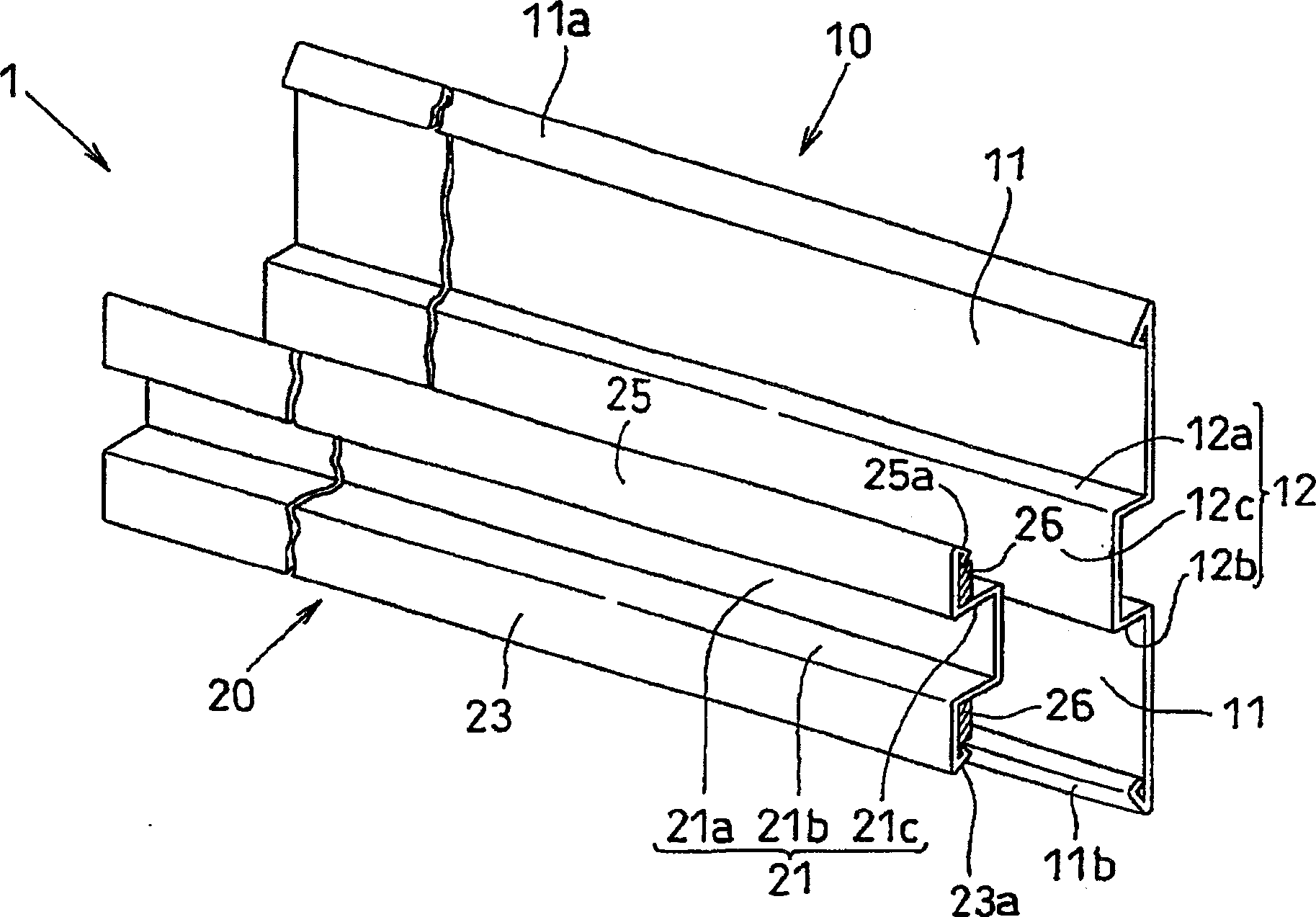
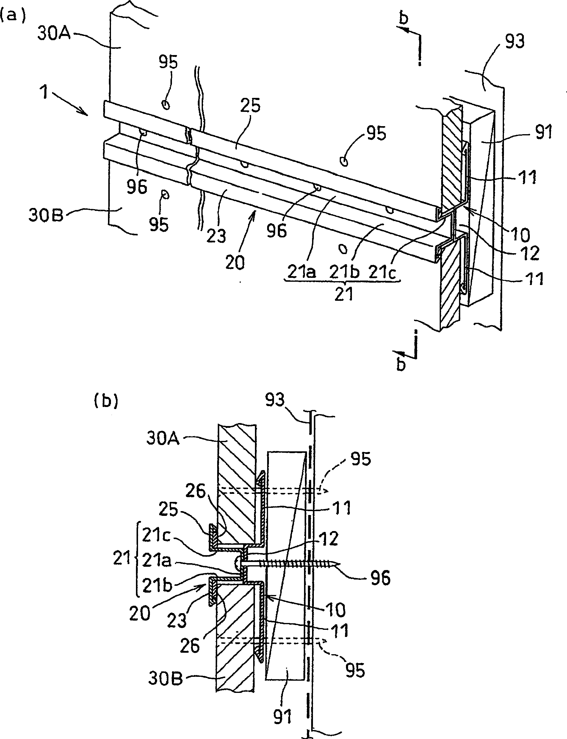
[0031] Hereinafter, preferred embodiments of the present invention will be described with reference to the drawings. figure 1 is a perspective view showing a seam according to one embodiment of the present invention; figure 2 a means to use figure 1 A perspective view of the construction configuration of the joint shown; figure 2 b is figure 2 The b—b line cross-section of a.

[0032] exist figure 2 In the shown outer wall construction structure, the outer wall panels 30A, 30B are attached to the horizontal strip 91 by driving nails 95 from the surface side, and the joint material 1 is fixed between the upper and lower outer wall panels 30A, 30B. seam piece 1 by figure 1 The two members shown, ie, the cap connector 10 and the seam cover 20 are constituted, and any one of them is formed by performing sheet metal working on a sheet of steel plate.

[0033] First, the hat connector 10 is composed of a substrate 11 serving as a fixing surface fixed to the horizontal b...


PUM


Abstract

The seam (1) is made of a hat-shaped connector (10) and a seam cover (20), and the hat-shaped connector (10) is composed of a base plate (11) fixed to the building skeleton side, and a base plate (11) from the base plate (11). ) constitutes a convex portion (12) protruding toward the surface side. The seam cover (20) has a seam groove (21) that covers the top surface (12c) of the convex portion (12) during construction, and extends downward from its lower end to be crimped on the outer wall panel (30B) during construction. ) the lower edge portion (23) of the surface, the back side of the lower edge portion (23) is pasted with an elastic water cut-off piece (26). Thereby, it is possible to provide a seamed material having a low manufacturing cost, easy construction, and a seam portion capable of forming a design property and a high water-cutting property.

Description

technical field [0001] The present invention relates to a joint that is fixed between upper and lower adjacent outer wall panels when the outer wall panels are installed on the outer wall of a building. Background technique [0002] In order to improve the design of the building's outer wall, external wall panels such as ceramics, which have been subjected to surface pattern treatment such as natural stone style / brick tile style, are often attached to the outer wall of the building. The installation method of the outer wall panel includes the horizontal installation method of attaching the longitudinal direction of the outer wall panel to the frame side as the horizontal direction (horizontal direction), and the vertical installation method of attaching the longitudinal direction of the outer wall panel to the frame side as the longitudinal direction (vertical direction) . Usually, the upper and lower end faces of the outer wall panels adopting the longitudinal installation...

Claims


Application Information

Patent Timeline
Patent Type & Authority Patents(China)
IPC IPC(8): E04F13/21E04F13/076
Inventor 伊藤博
Owner NICHIHA CORP
Why Eureka
Try Eureka