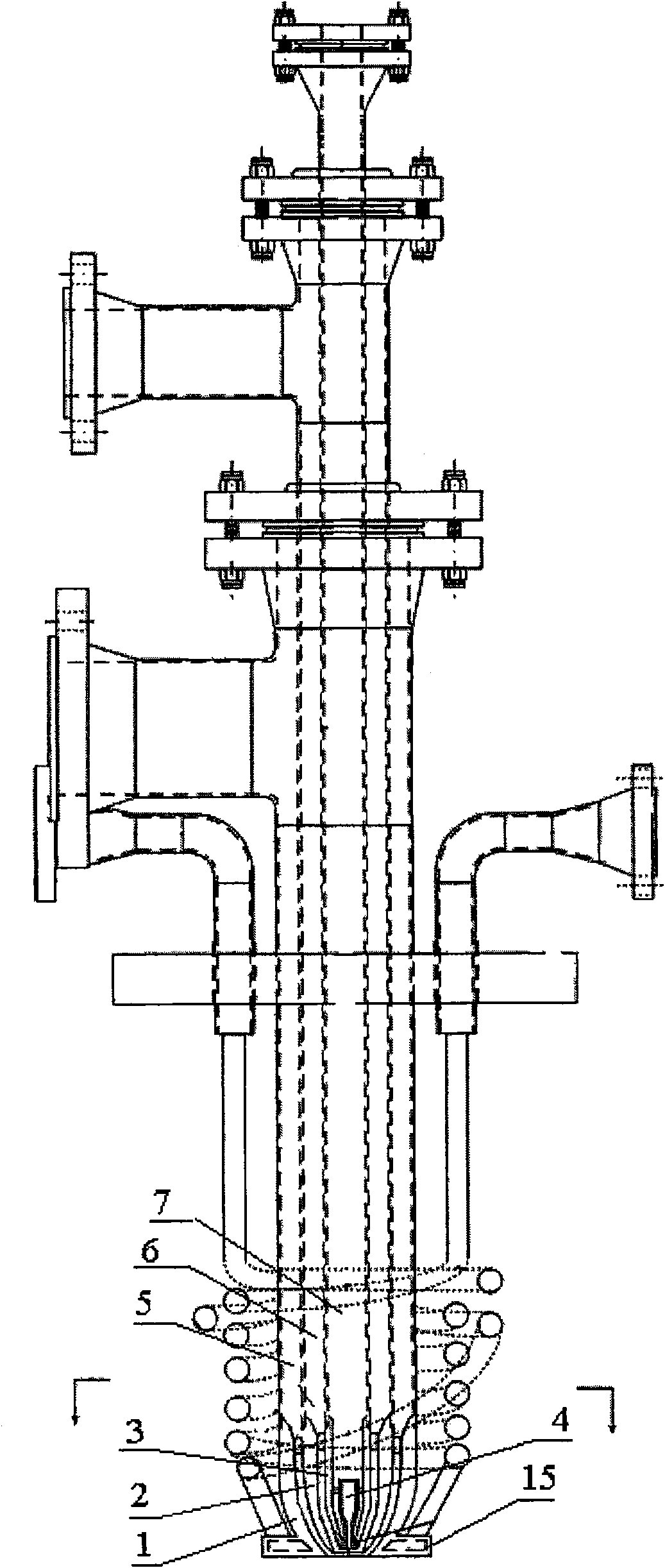
Multi-channel liquid stage fuel partial oxidation generating synthesis gas burner and uses thereof
A liquid fuel, multi-channel technology, applied in the direction of burners, lighting and heating equipment, etc., can solve the problems of burner cooling system leakage, short burner service life, poor burner atomization effect, etc., to achieve enhanced aerodynamics, Effect of long service life and improved atomization performance
- Summary
- Abstract
- Description
- Claims
- Application Information
AI Technical Summary
Problems solved by technology
Method used
Image

Examples
Embodiment 1
[0041] After the above-mentioned burner is installed in the gasifier disclosed in Chinese Patent No. 98110616.1, when the fuel is a coal-water slurry with a concentration of 61% (mass %), use 98% (volume) pure oxygen as the gasification agent to gasify The result is the effective gas component CO+H in the syngas 2 (vol%) 83.5%, ash residual carbon is 3%, and the continuous service life of the burner can reach 4 months, fully meeting the requirements of coal-water slurry gasification.
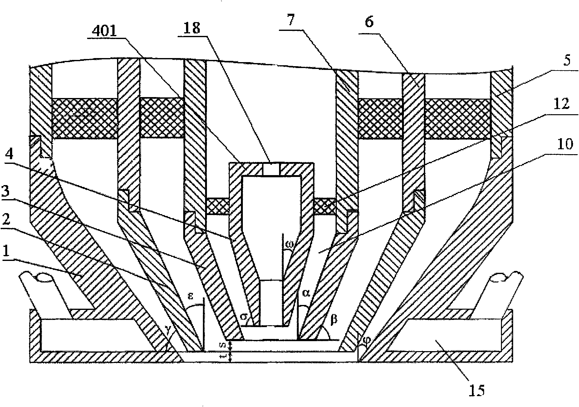
[0042] The structural parameters of said burner are as follows:
[0043] ω is 5°, σ is 85°; α is 5°, β is 80°; ε is 10°, γ is 40°; is 50°;
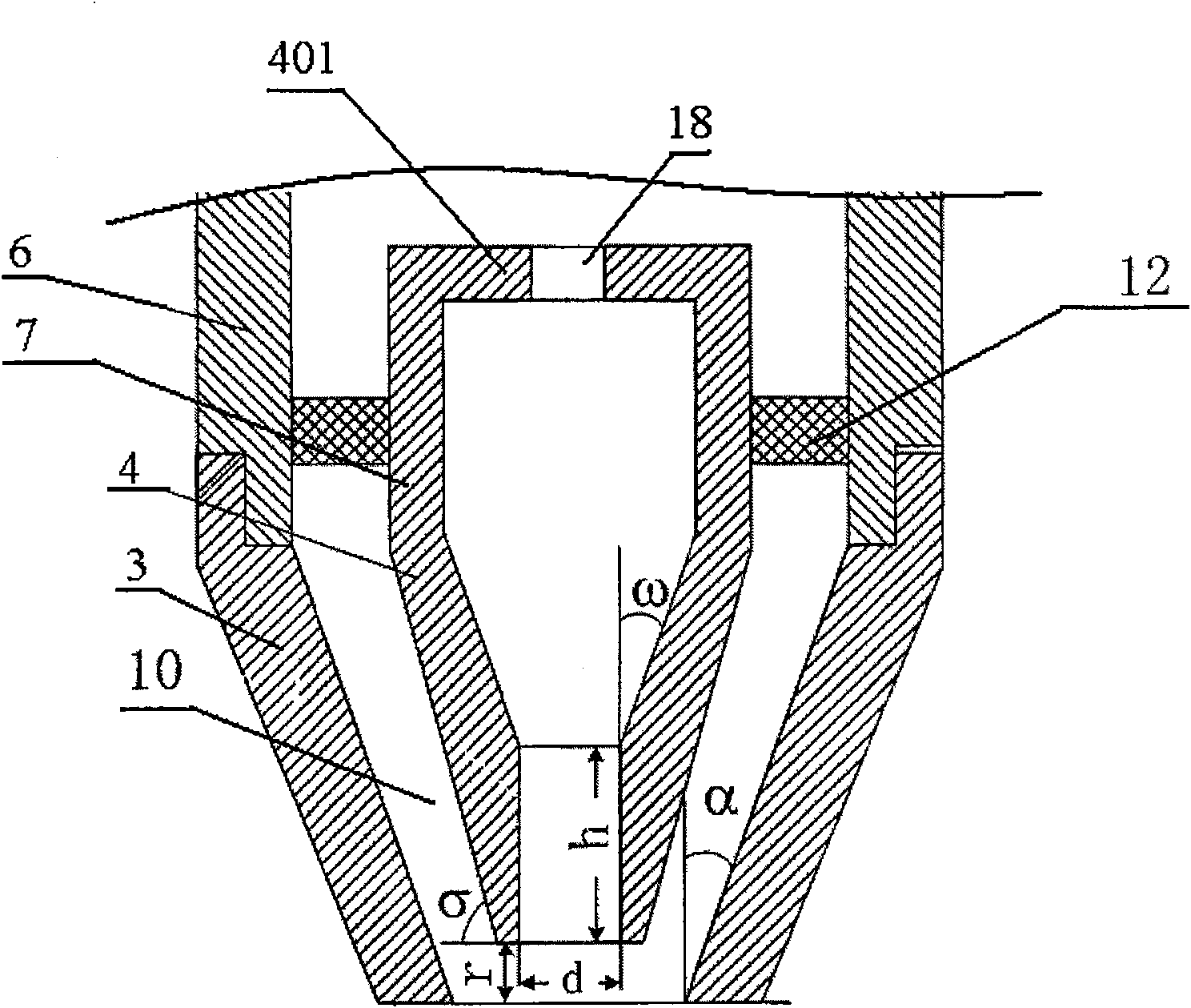
[0044] The ratio of the spout diameter d of the center nozzle 4 to the straight section height h of the spout, i.e. h: d=0.1;
[0045] The distance r between the nozzle end face of the center nozzle 4 and the nozzle end face of the inner ring nozzle 3 is 0.5 mm;
[0046] The distance s between the nozzle end face of the inner ring nozzle 3 and the nozz...
Embodiment 2
[0053]After the above-mentioned burner is installed in the gasifier disclosed in Chinese patent 98110616.1, when the fuel is a coal-water slurry with a concentration of 63% (mass %), with 99.6% pure oxygen as the gasification agent, the gasification result is a synthetic Effective gas composition in gas CO+H 2 (vol%) 85.5%, ash residual carbon is 3%, the continuous service life of the burner can reach 4 months, which fully meets the requirements of coal-water slurry gasification.
[0054] The structural parameters of said burner are as follows:
[0055] ω is 10°, σ is 80°; α is 10°, β is 70°; ε is 20°, γ is 30°; is 60°;
[0056] The ratio of the spout diameter d of the center nozzle 4 to the straight section height h of the spout, i.e. h: d=1;
[0057] The distance r between the nozzle end face of the center nozzle 4 and the nozzle end face of the inner ring nozzle 3 is 2 mm;
[0058] The distance s between the nozzle end face of the inner ring nozzle 3 and the nozzle end...
PUM
 Abstract
Description
Claims
Application Information
 - R&D Engineer
- R&D Manager
- IP Professional
- Industry Leading Data Capabilities
- Powerful AI technology
- Patent DNA Extraction
Browse by: Latest US Patents, China's latest patents, Technical Efficacy Thesaurus, Application Domain, Technology Topic.
© 2024 PatSnap. All rights reserved.Legal|Privacy policy|Modern Slavery Act Transparency Statement|Sitemap