Multi-spindle head replacement type machine tool

A technology of processing tools and multi-axis heads, which is applied in the direction of manufacturing tools, metal processing equipment, metal processing machinery parts, etc., can solve the problems that it is difficult to realize the high-speed rotation of the tool and the high-speed rotation of the output shaft 206, so as to improve the processing performance, The effect of improving operational efficiency

Inactive Publication Date: 2009-09-09
HONDA MOTOR CO LTD
View PDF7 Cites 0 Cited by
  • Summary
  • Abstract
  • Description
  • Claims
  • Application Information

AI Technical Summary

Problems solved by technology

When the rotation speed of the output shaft 206 increases, the spring 208 vibrates in the opening 204, thereby making it difficult to realize high-speed rotation of the output shaft 206
Furthermore, it is difficult to achieve high-speed rotation of the tool

Method used


Image

  • Multi-spindle head replacement type machine tool
  • Multi-spindle head replacement type machine tool
  • Multi-spindle head replacement type machine tool

Examples


Embodiment Construction

[0117] Exemplary embodiments of the present invention will be described with reference to the accompanying drawings.

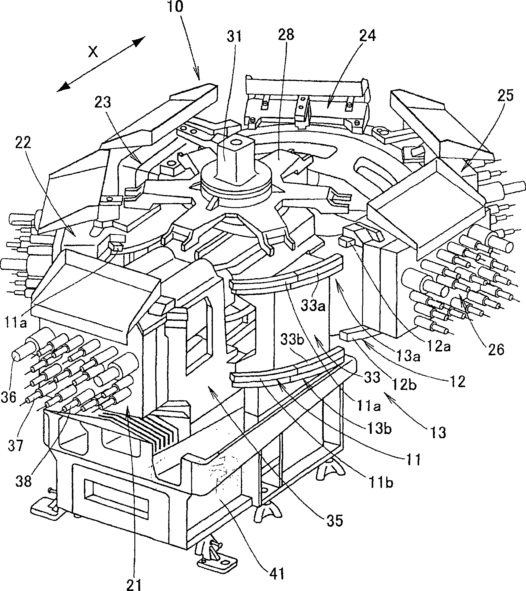
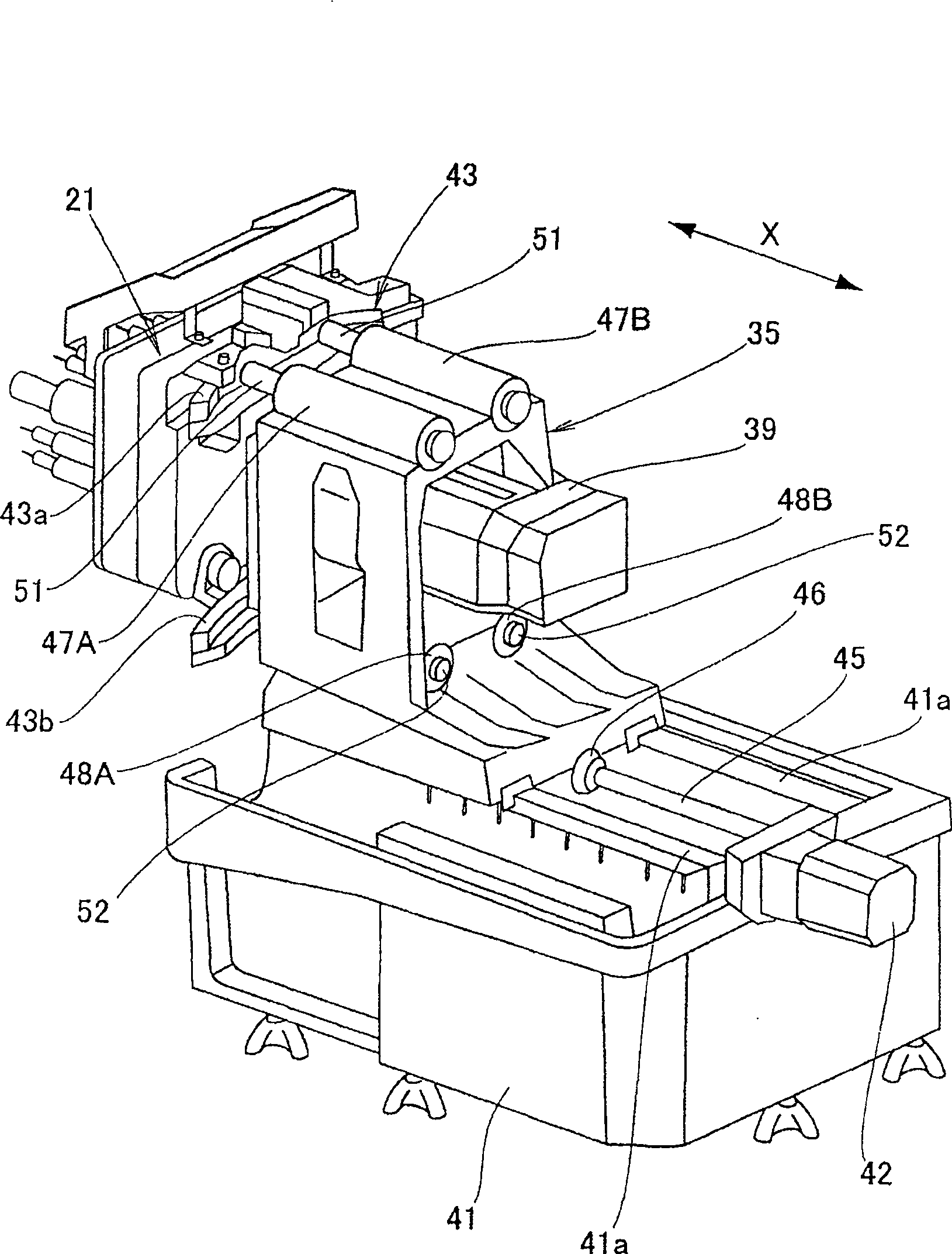
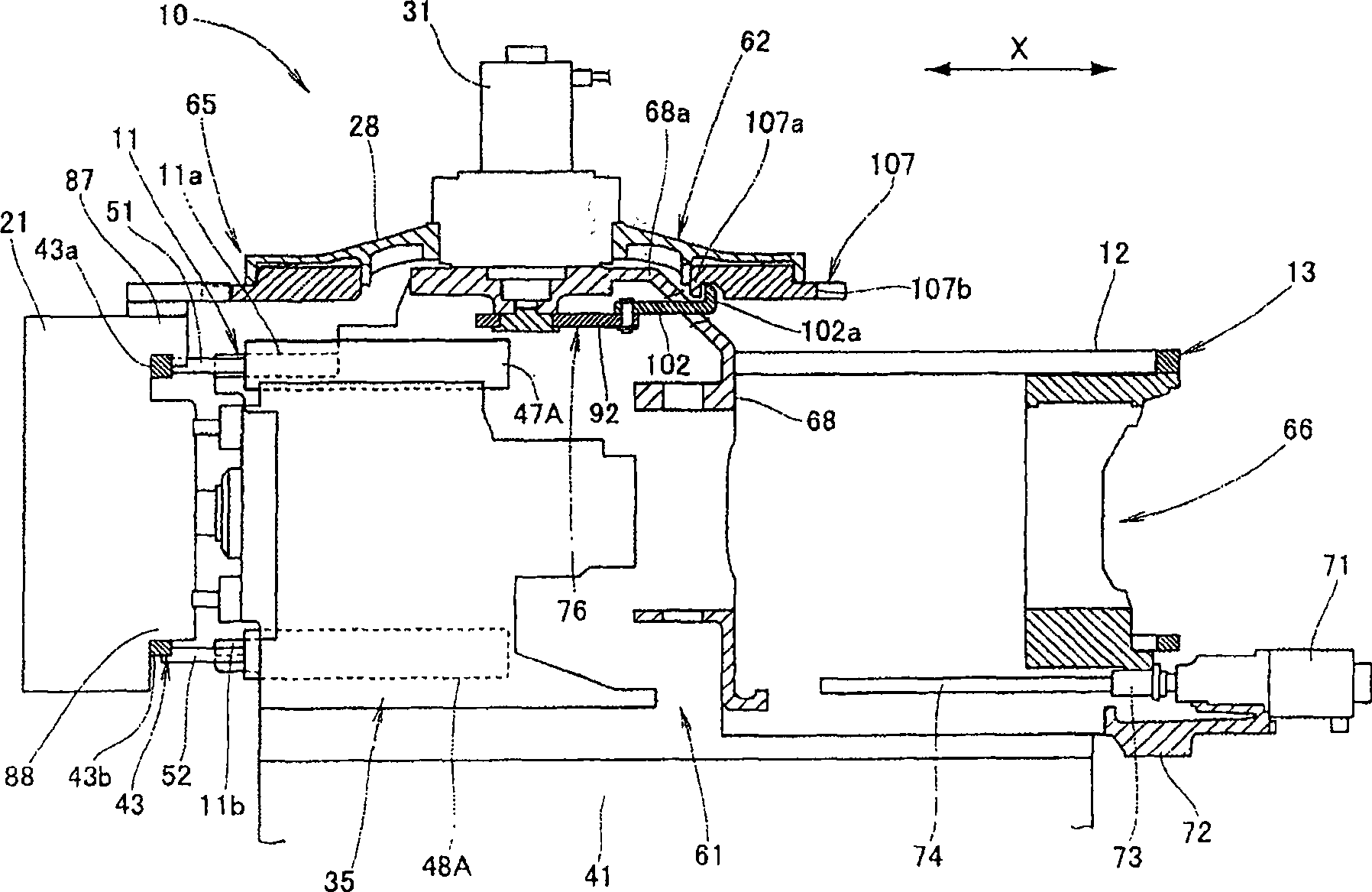
[0118] Preferably, the drawings are viewed based on the direction of the reference marks. figure 1 is a perspective view of a multi-spindle replaceable machining tool according to an embodiment of the present invention. In this multi-spindle head replaceable machining tool 10, a plurality of multi-spindle heads (referred to as “combined heads”) 21 to 26 are movably mounted to an annular rail 13, which can be divided into a first stationary rail 11 along the X-axis direction. and the second geostationary orbit 12. The first stationary rail 11 comprises an upper first stationary rail 11a and a lower first stationary rail 11b placed below the upper first stationary rail 11a, and the second stationary rail 12 comprises an upper second stationary rail 12a and a lower first stationary rail 11b placed below the upper first stationary rail 11a. The lower second stati...


PUM


Abstract

The present invention provides a multi-spindle head replaceable machining tool having a plurality of multi-spindle heads movably mounted on an annular track. When the workpiece is machined by driving the rotary tool by the machining unit, an unused multi-spindle head among the plurality of multi-spindle heads may be separated from the machining unit. In addition, the coupling means has an inner slide, a ball bearing mounted to an outer surface of the inner slide, an outer slide, and a coil spring that urges the outer slide toward the stopper element.

Description

technical field [0001] The present invention relates to a replaceable multi-spindle machining tool. Background technique [0002] It is known that a conventional replaceable multi-axis processing tool has a plurality of combination heads (multi-axis), wherein the plurality of combination heads are connected by an index table and move on a circular track (for example, refer to JP-A- 63-114807). In the alternative multi-spindle machining tool, the input shaft of one of the combination heads with rotary implements is detachably arranged on the output shaft of a machining unit. [0003] As in JP-A-63-114807 figure 2 As shown, in this multi-spindle machining tool 30, combined heads 42a to 42d as multi-spindle heads are movably disposed on upper and lower annular rails 40a and 40b. The combination heads 42a to 42d are engaged with an index table 44 arranged above the circular track 40a. When a rotary drive source 46 rotates the index table 44, the combination heads 42a to 42d ...

Claims


Application Information

Patent Timeline
Patent Type & Authority Patents(China)
IPC IPC(8): B23B39/16B23Q5/04B23Q3/157
Inventor 内川元纪宫城朋良平尾宪史后藤要本岛尚幸
Owner HONDA MOTOR CO LTD
Why Eureka
Try Eureka