Supercharge Your Innovation With Domain-Expert AI Agents!

Diversion device used in turbomachine having adjustable nozzle

A diversion device, turbine technology, applied in the direction of mechanical equipment, engine components, machines/engines, etc., can solve the problems that affect the reliability of use, leakage, and small gaps between rotating parts, so as to improve the reliability of use and prevent leakage Good, the effect of preventing gap leakage

Active Publication Date: 2009-09-30
CHONGQING JIANGJIN SHIPBUILDING IND
View PDF3 Cites 0 Cited by
  • Summary
  • Abstract
  • Description
  • Claims
  • Application Information

AI Technical Summary

Problems solved by technology

[0003] The main problem that the turbine of this kind of structure has existed for a long time is: the driving mechanism of the nozzle vane, which includes the crank, the rotating disc, the shift fork, etc. In the annular cavity, when the turbine is running, the high-temperature and high-pressure gas on the turbine side leaks into the cavity through the connection gap between the diaphragm, the turbine shell and the heat shield; and the crank of the drive mechanism must pass through the bearing shell The opening provided on the top, or on the turbine shell, or at the assembly connection between the turbine shell and the bearing shell is connected to the external drive source to facilitate the rotation and adjustment of the nozzle blades from the outside of the turbine, and the assembly of the drive mechanism at the opening must exist. There is a certain gap, so that the exhaust gas with a certain amount of energy in the use of the turbine will inevitably leak out of these gaps. First, the leakage of the exhaust gas will cause a decrease in the efficiency of the exhaust gas and pollute the environment. The driving mechanism of the variable nozzle vane has high temperature and the deposition of exhaust gas pollutants, which affects its reliability
[0004] In the past, the anti-leakage measures adopted for this part of the turbine with adjustable nozzles are usually by strengthening the "blocking" of the mechanical seal, such as reducing the matching size, adding piston rings, etc. for sealing. These sealing devices are installed in the turbine. It is more effective when running at low speed, but the effect is not good at high speed; and this kind of mechanical seal is easy to lock due to thermal deformation due to the small gap between the rotating parts and the transmission parts are always in a high temperature environment, resulting in The turbine does not work properly, and artificially increases the number of parts and the difficulty of assembly

Method used


Image

  • Diversion device used in turbomachine having adjustable nozzle
  • Diversion device used in turbomachine having adjustable nozzle

Examples


Embodiment

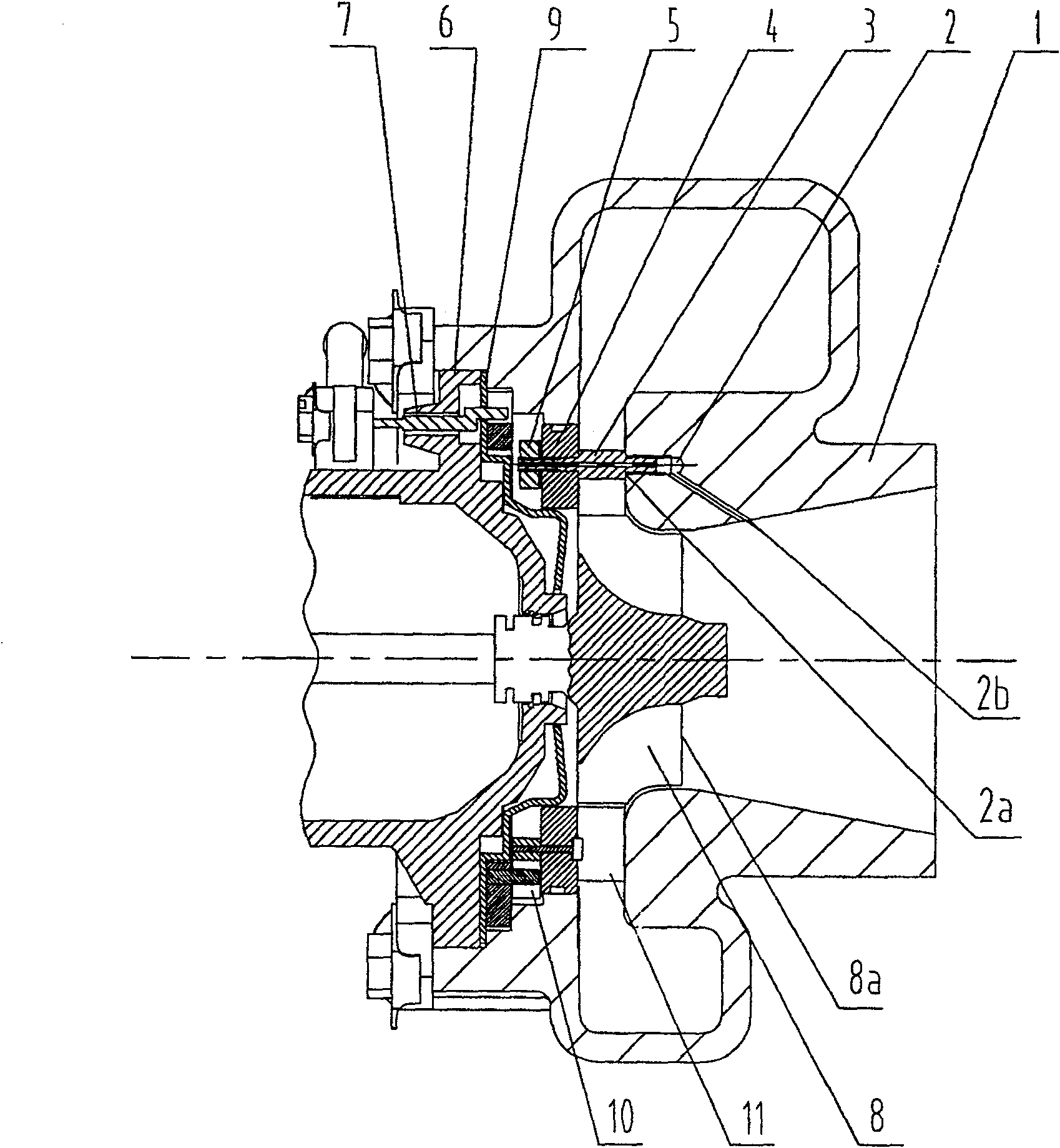
[0017] Example: see figure 1 , figure 2 , a flow guide device for a single-stage turbine with an adjustable nozzle, characterized in that: the flow guide device includes a flow guide channel 2 and a positioning tube 3, wherein one end of the positioning tube 3 is connected to the guide channel The diversion inlet 2a of 2 is connected.

[0018] Described deflector is arranged on the inner side of air outlet 1a of the turbine shell 1 of turbomachine and the driving mechanism 10 of some nozzle vanes 11 on the circumference of the jet passage in the turbine shell 1, consists of turbine shell 1, bearing shell 6, partition Between the annular cavity formed by the connection between the plate 4 and the heat shield 9 .

[0019] The guide channel 2 is arranged in the shell of the turbine shell 1, the guide inlet 2a is set on the outer wall of the jet channel of the turbine shell 1, and the guide outlet 2b is set on the The inner side surface of the air outlet 1a of the turbine shel...


PUM


Abstract

The invention relates to a flow guiding device for a turbine with an adjustable nozzle, characterized in that: the flow guiding device comprises a flow guiding channel (2) and a positioning tube (3), wherein one end of the positioning tube (3) It is connected with the diversion inlet (2a) of the diversion channel (2). The flow guiding device for a single-stage turbine with an adjustable nozzle has a simple, ingenious and reasonable structure, good leakage prevention effect, and can improve the long-term reliability of the driving mechanism of the nozzle vane in a high-temperature environment.

Description

technical field [0001] The invention relates to an anti-leakage device for a turbine with an adjustable nozzle, in particular to a flow diversion and anti-leakage device for a single-stage turbine with an adjustable nozzle for radial flow and mixed flow. Background technique [0002] At present, the basic structure of the radial flow and mixed flow single-stage turbines with adjustable nozzles includes: a turbine casing, a single set of bladed turbines assembled in the turbine casing, a bearing casing fixedly connected to the turbine casing, fixed on the bearing The shell is located in the heat shield at the front end of the turbine shell, the inner cylindrical surface is in contact with the heat shield, and the outer cylindrical surface is sealed with the inner side of the turbine shell, and the partition plate is arranged between the circular step at the outer end of the heat shield and the turbine shell One end of the rotating disk passes through the hole on the heat shie...

Claims


Application Information

Patent Timeline
Patent Type & Authority Patents(China)
IPC IPC(8): F01D17/16
Inventor 刘红丹刘雅黔徐文江
Owner CHONGQING JIANGJIN SHIPBUILDING IND
Features
  • R&D
  • Intellectual Property
  • Life Sciences
  • Materials
  • Tech Scout
  • Unparalleled Data Quality
  • Higher Quality Content
  • 60% Fewer Hallucinations
Learn More