Supercharge Your Innovation With Domain-Expert AI Agents!

Air humidity removing device

A humidity and gas technology, which is applied in the field of gas humidity removal devices, can solve problems such as system shutdown, performance cannot be improved, and dehumidification effect is discounted

Active Publication Date: 2009-09-30
蔡瑞云
View PDF8 Cites 0 Cited by
  • Summary
  • Abstract
  • Description
  • Claims
  • Application Information

AI Technical Summary

Problems solved by technology

[0004] 1. High humidity The moisture attached to the evaporator 2 is relatively increased, and it is often in the environment, and the suspended particles are attached to the surface of the evaporator 2, causing the condensed water to stay on the surface of the evaporator 2 for a longer time, and the low temperature state is easy Icing, once it freezes, not only the dehumidification effect will be reduced but also the gas path will be easily blocked. After a vicious cycle, the entire evaporator will form a large ice block that is completely blocked and lose the dehumidification effect
[0005] 2. When the evaporator 2 freezes, the whole system will be unbalanced, that is, the load of the compressor compressing the cold coal will increase, and the operating current will increase relatively, which will not only form virtual work, but also delay the evaporation of the refrigerant, causing the compressor to work Ice will cause the compressor to run insufficiently lubricated and burn the coil, causing the system to shut down
[0006] 3. When the evaporator 2 freezes, the system needs to be completely melted before restarting the system. This is time-consuming and the performance cannot be improved.

Method used


Image

  • Air humidity removing device
  • Air humidity removing device
  • Air humidity removing device

Examples


Embodiment Construction

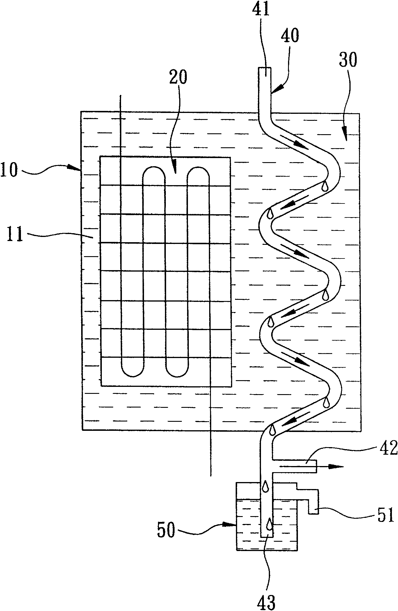
[0013] Below in conjunction with accompanying drawing and embodiment the present invention is described in detail:

[0014] like figure 2 As shown, the first preferred embodiment of the gas humidity removal device of the present invention includes: a body 10, an evaporator 20 installed inside the body 10, a cooling liquid medium 30 filled in the body 10, a A gas pipeline 40 passing through the main body 10 and a water collection dish 50 disposed at the bottom of the main body 10 .

[0015] The body 10 has a chamber 11 .

[0016] The evaporator 20 is installed in the chamber 11 of the body 10 .

[0017] The cooling liquid medium 30 of this embodiment can be water, and it is pre-filled in the chamber 11 of the body 10, and the liquid level is higher than the evaporator 20, so that the evaporator 20 is fully immersed in the cooling liquid medium 30 .

[0018] The gas pipeline 40 runs through the body 10, and has an air inlet 41 protruding from the top of the body 10, a gas o...


PUM


Abstract

The invention discloses a gas humidity removal device, which mainly comprises a body filled with a cooling liquid medium, an evaporator immersed in the cooling liquid medium and a gas pipeline immersed in the cooling liquid medium. The gas pipeline has at least one air inlet, at least one gas outlet, and a water outlet. When the evaporator lowers the cooling liquid medium to a predetermined temperature, the humid air circulating in the gas pipeline will condense water droplets along the The pipe wall flows down and then discharged, thereby reducing the humidity of the gas circulating in the gas pipeline.

Description

technical field [0001] The invention relates to a gas humidity control device, in particular to a gas humidity removal device. Background technique [0002] like figure 1 As shown, there is an existing gas humidity removal device, which mainly flows the circulating gas 1 through an evaporator 2 with a lower temperature, so that the moisture contained in the gas condenses into water droplets, and then freely drips and collects discharge, so as to achieve the dehumidification effect. [0003] The above-mentioned dehumidification method is widely used, but it is only limited to the general natural environment. If it is applied to the environment with high humidity, it will have the following defects: [0004] 1. High humidity The moisture attached to the evaporator 2 is relatively increased, and it is often in the environment, and the suspended particles are attached to the surface of the evaporator 2, causing the condensed water to stay on the surface of the evaporator 2 for...

Claims


Application Information

Patent Timeline
Patent Type & Authority Patents(China)
IPC IPC(8): F24F13/22
Inventor 钟永村蔡世良
Owner 蔡瑞云
Features
  • R&D
  • Intellectual Property
  • Life Sciences
  • Materials
  • Tech Scout
  • Unparalleled Data Quality
  • Higher Quality Content
  • 60% Fewer Hallucinations
Learn More