Flowmeter

A flowmeter and fluid technology, applied in the field of flowmeters, can solve the problems of increased high-frequency noise, increased power consumption, and increased circuit size.

Inactive Publication Date: 2009-09-30
PANASONIC CORP
View PDF8 Cites 1 Cited by
  • Summary
  • Abstract
  • Description
  • Claims
  • Application Information

AI Technical Summary

Problems solved by technology

When the operation clock of the timer 54 is increased so as to have a higher frequency, various problems such as increased power consumption, increased high-frequency noise, and increased circuit size occur.

Method used


Image

  • Flowmeter
  • Flowmeter
  • Flowmeter

Examples


Embodiment 1

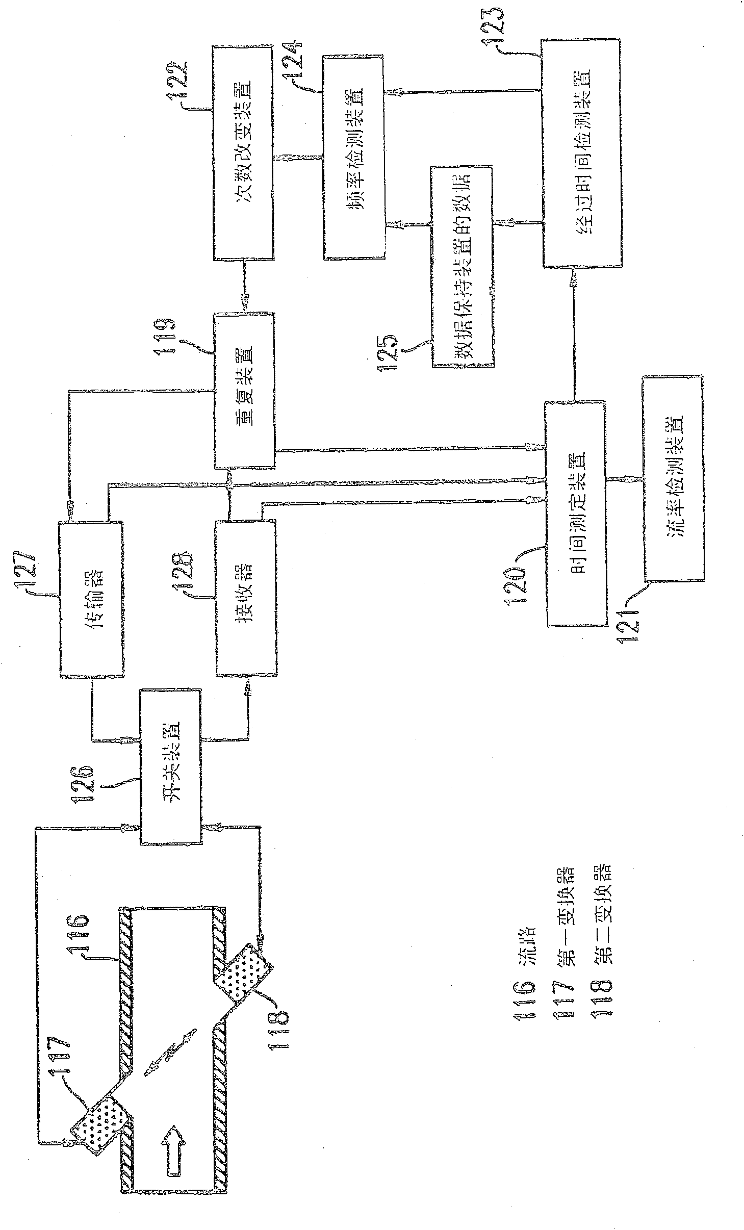
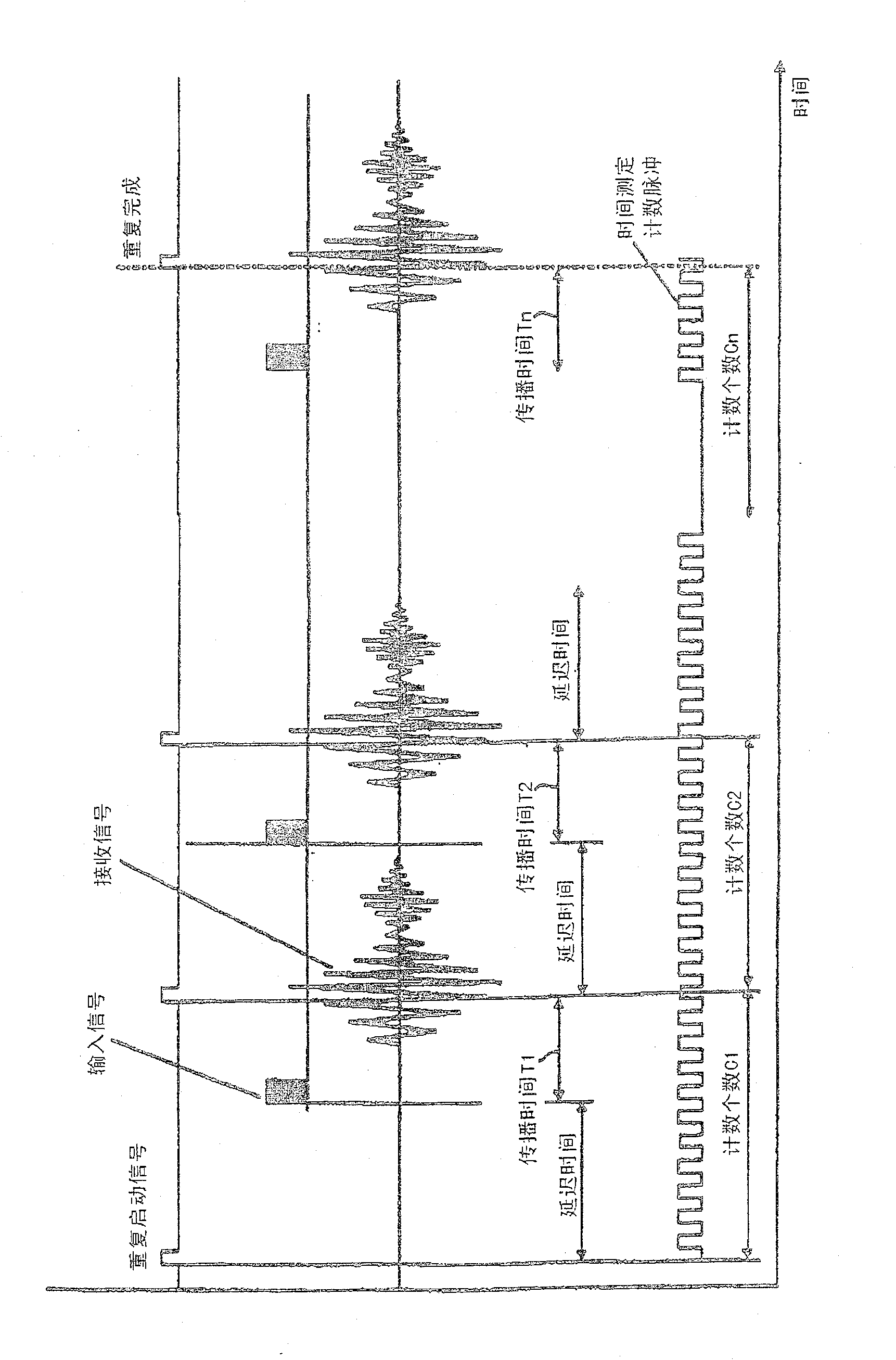
[0153] figure 1 It is a block diagram showing a flow meter according to Embodiment 1 of the present invention. in figure 1 In, reference numeral 117 is a first transmission / reception device, which is arranged in the flow path 116 and serves as a transmission / reception device for transmitting / receiving signals by using the transmission of ultrasonic waves as a state change in the fluid. Reference numeral 118 is a second transmission / reception device as a transmission / reception device. Reference numeral 119 is a repeating device for repeatedly performing signal propagation between the first transmission / reception device 117 and the second transmission / reception device 118. Reference numeral 120 is a time measuring device, which is used to measure the propagation time of ultrasonic waves propagated during the repetition of the repetition device 119. Reference numeral 121 is a flow rate detecting device for detecting the flow rate based on the value from the time measuring device 1...

Embodiment 2

[0159] Figure 6 It is a flowchart showing the operation process of the flow meter according to the second embodiment of the present invention. Embodiment 2 is different from Embodiment 1, in that the process of Embodiment 2 is structured so that the number of repetitions measured according to the frequency obtained by the frequency detection device is used in the next flow rate measurement. The structure of the flow meter in Example 2 is the same as figure 1 Same as shown in.

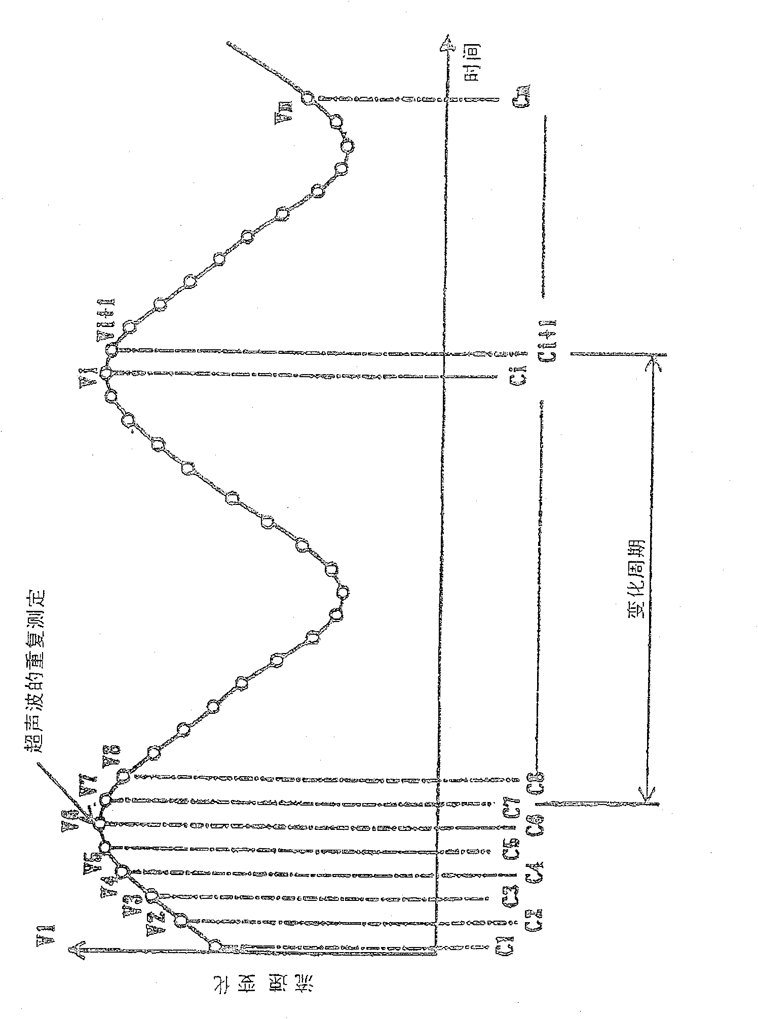
[0160] Such as Figure 6 As shown, the propagation time T1 of the ultrasonic wave propagating from the first transducer is measured, and the measurement information C i Stored in the data holding device. Then, the propagation time T2 of the ultrasonic wave propagating from the second transducer is measured, and the flow velocity and flow rate are calculated based on the times T1 and T2. Then, using the method described in Example 1, the information C is measured based on the stored time i The frequency o...

Embodiment 3

[0163] Figure 7 It is a block diagram of a flow meter according to Embodiment 3 of the present invention. Embodiment 3 is different from Embodiment 1, in which the flow meter of Embodiment 3 includes: a flow rate change identification device 129 for determining the magnitude of the flow rate change detected by the flow rate detection device 121; and a frequency changing device 122 for The number of repetitions is changed so that the flow rate change recognized by the flow rate change recognition device 129 is reduced, and the flow rate change recognition device 129 is made to operate using the standard deviation of the flow rate.

[0164] Such as Figure 8 As shown in the flowchart, first measure the flow rate Qi. When the flow rate is equal to or greater than the predetermined value Qm (for example, 100 liters / hour), the number of repetitions remains unchanged. When the flow rate is lower than the predetermined value Qm, the standard deviation Hi is obtained based on n pieces o...


PUM


Abstract

A flowmeter comprising: a transmission / reception device for transmitting / receiving a signal using a state change of a fluid flowing in a flow path; a time measuring device for measuring the time during which the transmission / reception device is transmitting / receiving a signal Propagation time of fluid state change; flow rate detecting means for detecting the flow rate of the fluid based on the propagation time measured by the time measuring means; change detecting means for detecting the pressure in the flow path based on the output of the transmission / receiving means change; measurement control means for starting measurement synchronously with the moment when the change detection means detects a pressure change, and selection means for switching the output of the transmission / reception means so that the output of the transmission / reception means is used to detect fluid flow rate and is used to detect pressure changes in the flow path.

Description

[0001] This application is a divisional application of a Chinese patent application with an application date of June 23, 2000, an application number of 00809439.X, and an invention title of "flowmeter". Technical field [0002] The invention relates to a flow meter for measuring the flow rate of liquid or air. The invention also relates to a device capable of measuring the flow rate value in an accurate manner even when there is a pressure or temperature change. Background technique [0003] Traditionally, this type of flowmeter is well known, for example, such a flowmeter is described in Japanese Laid-open Patent No. 9-15006. Such as Figure 64 As shown, the flowmeter includes: a sampling program 2, which is used to read a measurement value from an analog flow sensor 1 that measures gas flow rate with a predetermined first sampling time as a time interval; and a gas consumption calculation program 3, This program is used to calculate the flow rate of the consumed gas at a predete...

Claims


Application Information

Patent Timeline
Patent Type & Authority Patents(China)
IPC IPC(8): G01F1/66G01F1/72G01P5/24G01F15/02
Inventor 梅景康裕长冈行夫江口修安倍秀二中林裕治黄地谦三芝文一足立明久桥本雅彦佐藤利春藤井裕史
Owner PANASONIC CORP
Why Eureka
Try Eureka