Zooming lens module group

A zoom lens and lens module technology, applied in installation, optics, instruments, etc., can solve the problems of reducing production costs, disadvantages, and complex mechanical structures, and achieve the effects of reducing production costs, simplifying structures, and reducing volume

Inactive Publication Date: 2009-09-30
HONG FU JIN PRECISION IND (SHENZHEN) CO LTD +1
View PDF7 Cites 4 Cited by
  • Summary
  • Abstract
  • Description
  • Claims
  • Application Information

AI Technical Summary

Problems solved by technology

The mechanical structure of this type of zoom lens module is complex and the volume is large. Usually, a combination of various parts is required to mechanically drive the lens barrel loaded with lenses to move to achieve zooming. This is not conducive to reducing the size of the lens module and making it Combined with portable electronic devices, it cannot meet the increasing light, thin and small development needs of portable electronic devices, and it is also not conducive to reducing production costs

Method used


Image

  • Zooming lens module group
  • Zooming lens module group
  • Zooming lens module group

Examples


Embodiment Construction

[0011] The zoom lens module provided by the embodiment of the technical solution will be further described below in conjunction with the accompanying drawings.

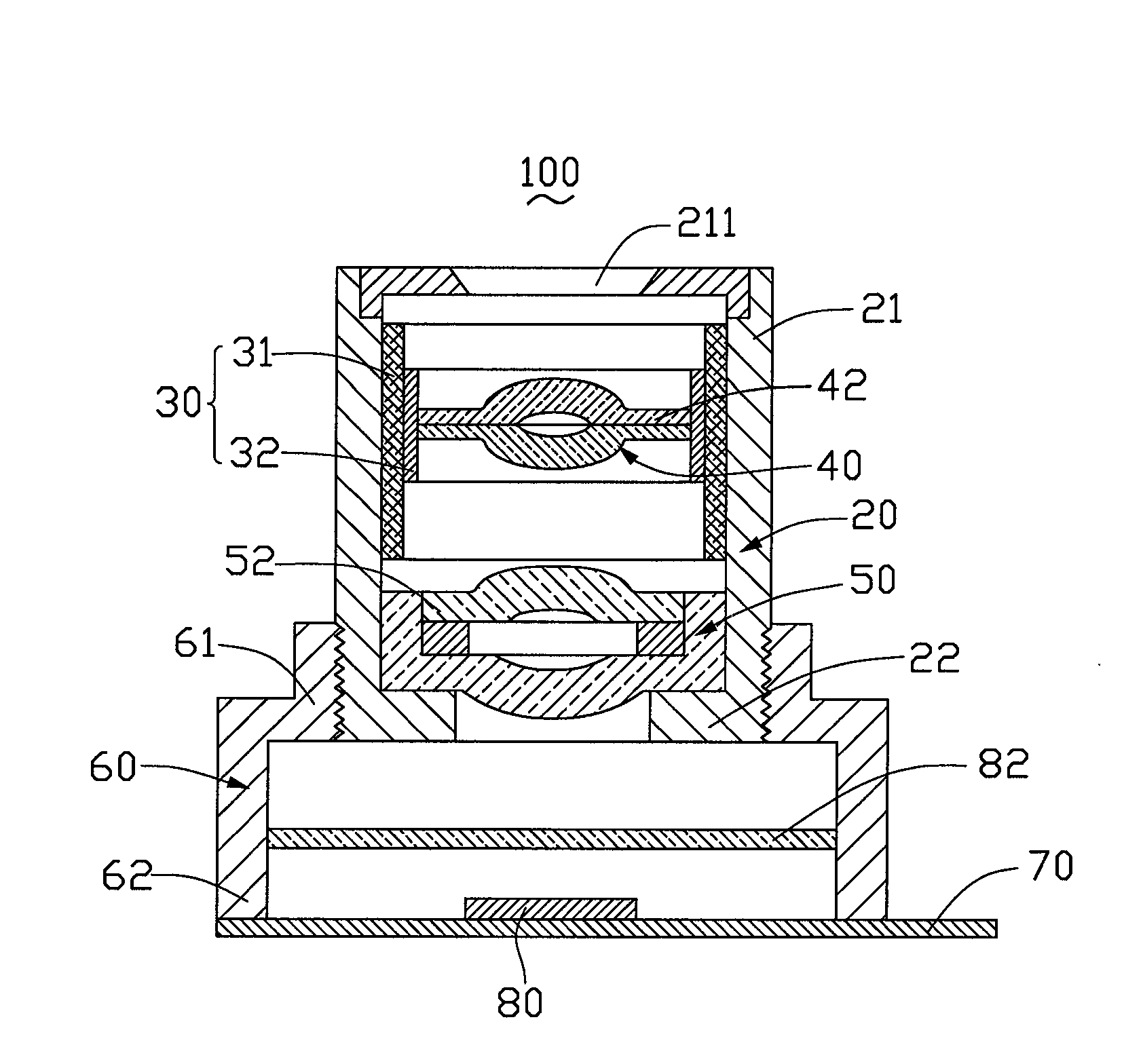
[0012] see figure 1 Embodiment 1 of the technical solution provides a zoom lens module 100 , which includes a lens barrel 20 , a piezoelectric actuator 30 , a first lens module 40 , a second lens module 50 and a lens base 60 .

[0013] The lens barrel 20 is a cylinder for accommodating the piezoelectric actuator 30 , the first lens module 40 and the second lens module 50 . The lens barrel 20 has a first end 21 and a second end 22, the first end 21 is provided with a light entrance hole 211, light can enter the zoom lens module 100 through the light entrance hole 211, and pass through the first The lens module 40 and the second lens module 50 . The inner wall of the first end 21 may be provided with threads for cooperating with and fixing the piezoelectric actuator 30, and the outer wall of the second end 22 may be p...


PUM


Abstract

The invention relates to a zoom lens module, which includes a lens barrel, a piezoelectric actuator accommodated in the lens barrel, a first lens module and a second lens module. The piezoelectric actuator and the second lens module are sequentially fixed on the lens barrel. The piezoelectric actuator includes a piezoelectric ceramic part and a sliding part matched with the piezoelectric ceramic part. The piezoelectric ceramic part is fixed on the lens barrel, and the sliding part is arranged between the piezoelectric ceramic part and the first lens mold. between the groups, and is connected with the piezoelectric ceramic piece. The first lens module is fixed on the slider, and the piezoelectric ceramic is used to drive the slider to move relative to the piezoelectric ceramic under the action of voltage, thereby driving the first lens module to move along the optical path relative to the second lens module. Axis direction movement. The zoom lens module has a simple structure, can effectively reduce the volume of the zoom lens module, and reduce production costs.

Description

technical field [0001] The invention relates to a lens module, in particular to a zoom lens module. Background technique [0002] Digital image capture technology has been widely used by people, especially in recent years, portable electronic devices such as mobile phones, personal digital assistants and notebook computers have rapidly developed towards high performance and multi-functionality. Digital image capture technology and such portable electronic devices The combination of mobile multimedia technology has become an important development direction. [0003] With the continuous development of lens module technology, the miniature lens module used in the digital image capture technology of portable electronic devices in the prior art has gradually changed from a traditional fixed focus system to a high-end zoom system. However, a traditional zoom lens module usually uses a voice coil motor or a stepping motor as a driving source, and cooperates with a mechanical struc...

Claims


Application Information

Patent Timeline
Patent Type & Authority Patents(China)
IPC IPC(8): G02B15/14G02B9/12G02B1/11G02B7/09H02N2/00
CPCG02B7/102G02B13/009
Inventor 林瑞兴
Owner HONG FU JIN PRECISION IND (SHENZHEN) CO LTD
Why Eureka
Try Eureka