Optical recording apparatus, optical recording method

A technology for optical recording and optical recording media, which is applied to optical recording heads, optical recording carriers, recording/reproducing by optical methods, etc., and can solve the problems of high laser power and difficult camera-integrated optical recording devices.

Active Publication Date: 2009-09-30
TAIYO YUDEN KK
View PDF4 Cites 0 Cited by
  • Summary
  • Abstract
  • Description
  • Claims
  • Application Information

AI Technical Summary

Problems solved by technology

However, in conventional optical recording media, there is a problem that the laser power required for recording the L1 layer is large, and it is difficult to use it in a battery-driven camera-integrated optical recording device.

Method used


Image

  • Optical recording apparatus, optical recording method
  • Optical recording apparatus, optical recording method
  • Optical recording apparatus, optical recording method

Examples


no. 1 approach

[0040] (optical recording and reproducing device)

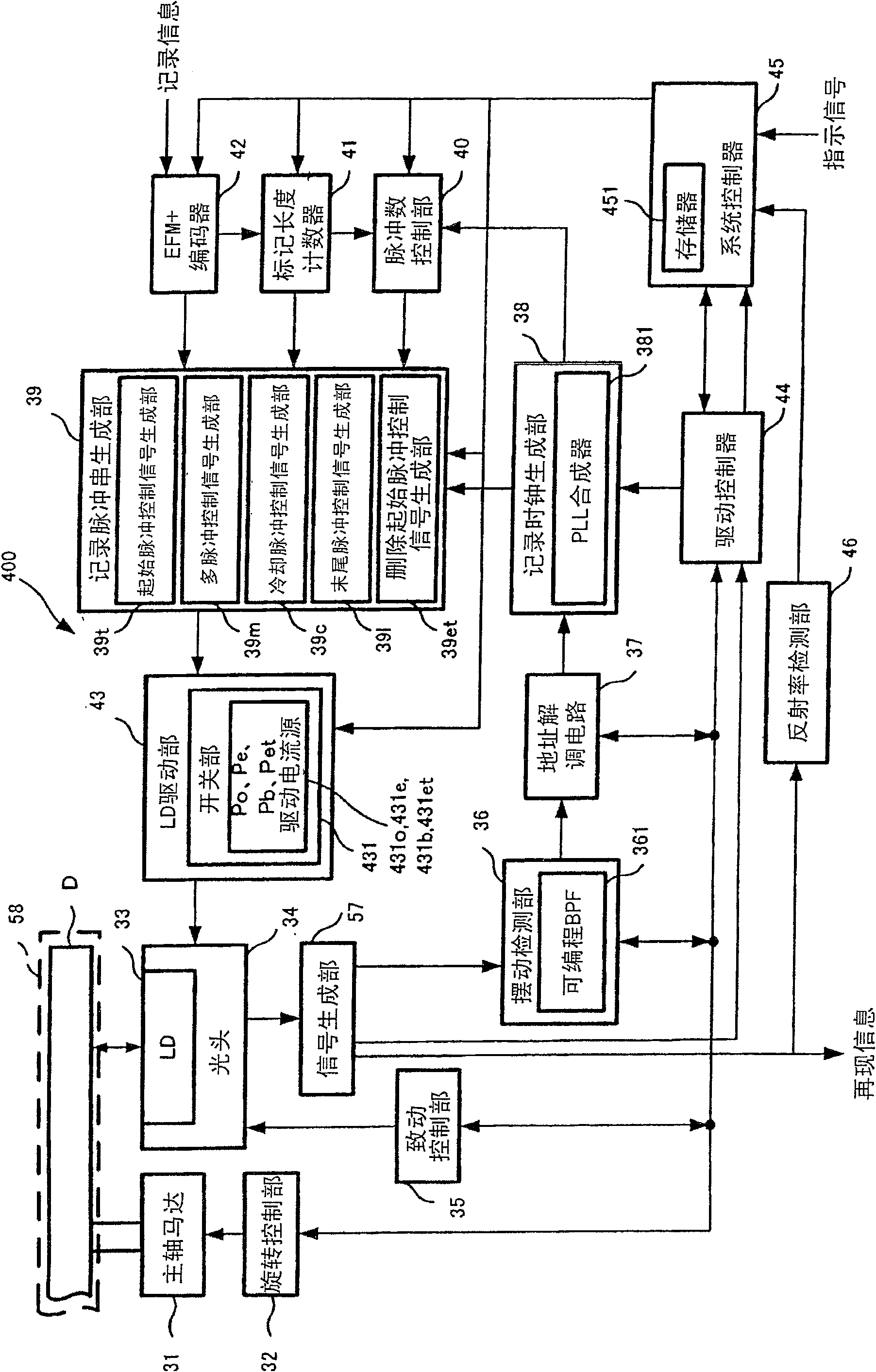
[0041] figure 1 One embodiment of the optical recording and reproducing device of the present invention is shown.

[0042] First, the spindle motor 31 rotates the optical recording medium D. As shown in FIG. The rotation control unit 32 controls so that the rotation speed of the spindle motor 31 becomes a recording linear velocity corresponding to a target recording velocity. In addition, a semiconductor laser (LD) 33 for recording, reproducing or erasing the optical recording medium D is movably arranged on the radial direction of the optical recording medium D, and has an objective lens (not shown) that condenses and irradiates laser light from the LD33. ) and an optical head 34 such as four-divided light-receiving elements (not shown).

[0043] Furthermore, as the light source for recording used in the optical recording and reproducing apparatus of the present embodiment, a high-intensity light source such as a laser be...

no. 1 example

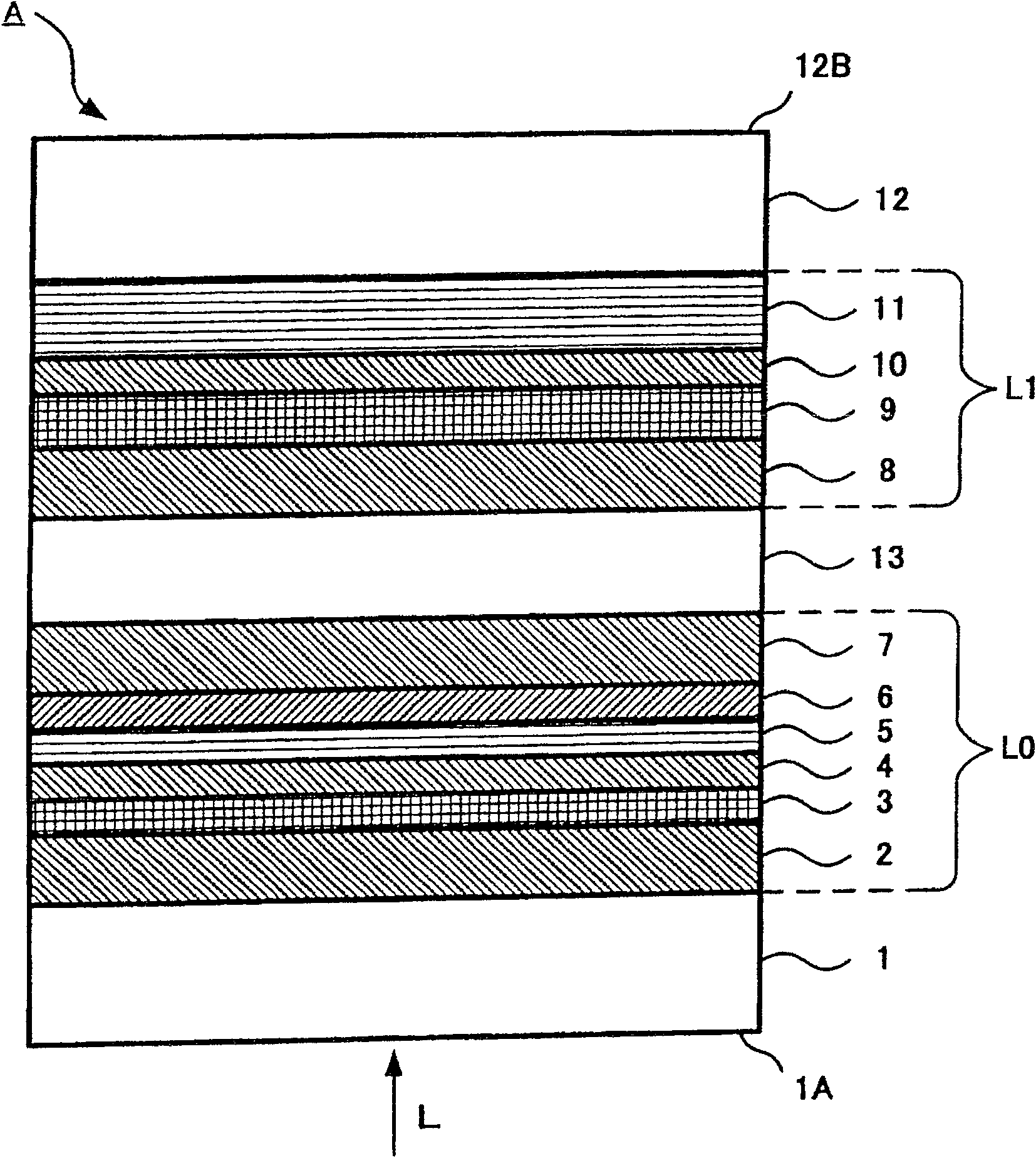
[0109] Recording is performed on the L0 layer using the first recording pulse train P1, and recording is performed on the L1 layer using the second recording pulse train P2. The recording linear velocity is 7.5m / s (double speed of DVD).

[0110] The optimum recording power Po0 in the L0 layer is 20 mW, and the jitter at this time is 8.7%. The optimum recording power refers to the recording power at which the jitter shows the minimum value. The optimum recording power Po1 in the L1 layer is 32 mW, and the jitter at this time is 8.5%. The power ratio (Po1 / Po0) of the optimum recording power Po0 of the L0 layer and the optimum recording power Po1 of the L1 layer is 1.6. The modulation degree of the L1 layer is 55%. Here, if the degree of modulation shows a value of 50% or more, it meets the specification and is preferable. These results and the results of the second and third examples described later are shown in Figure 7 .

no. 2 example

[0112] Recording is performed by the first recording pulse train P1 on the L0 layer, and recording is performed by the first recording pulse train P1 on the L1 layer. The recording linear velocity is 7.5m / s (double speed of DVD).

[0113] The optimum recording power Po0 in the L0 layer is 20 mW, and the jitter at this time is 8.7%. The optimum recording power Po1 in the L1 layer is 37 mW, and the jitter at this time is 8.3%. The power ratio (Po1 / Po0) of the optimum recording power Po0 of the L0 layer and the optimum recording power Po1 of the L1 layer is 1.85. The degree of modulation of the L1 layer is 53%, showing a good value.


PUM


Abstract

The present invention provides an optical recording device, an optical recording method, and an optical recording medium capable of recording on the rear unit recording layer with low power in a phase-change optical recording medium having a plurality of unit recording layers. The reproduction unit for the optical recording device reads identification information from the optical recording medium (D). The recording burst generation unit (39) generates, based on the read first identification information indicating the first recording condition for the first unit recording layer and second identification information indicating the second recording condition for the second unit recording layer, respectively First and second recording bursts are generated. The recording unit (400) performs recording by irradiating light corresponding to the first recording pulse train to the first unit recording layer and irradiating light corresponding to the second recording pulse train to the second unit recording layer.

Description

technical field [0001] The present invention relates to an optical recording device, an optical recording method, and an optical recording medium for recording information on an optical recording medium by irradiation of light (for example, laser light). In particular, the present invention provides an optical recording device, an optical recording method, and an optical recording medium capable of recording well on a double-layer phase-change optical recording medium having two rewritable recording films even with relatively low recording power. recording medium. Background technique [0002] The phase-change optical recording medium is a medium that can rewrite information by using the reversible phenomenon between the crystalline phase and the amorphous phase, such as CD-RW (Compact Disc Rewritable Disc), DVD-RW ( rewritable digital versatile disk), DVD-RAM (rewritable random access digital versatile disk). Among them, DVD-RW and DVD-RAM are mainly used for recording an...

Claims


Application Information

Patent Timeline
Patent Type & Authority Patents(China)
IPC IPC(8): G11B7/00G11B7/007G11B7/125G11B20/12
Inventor 松本郁夫
Owner TAIYO YUDEN KK
Why Eureka
Try Eureka