Sub-roller mechanism of computer plain flat knitter

A flat knitting machine and sub-roller technology, used in knitting, weft knitting, textiles and papermaking, etc., can solve the problems of large power transmission loss, affecting the traction effect, left and right movement, etc., to achieve low power transmission loss. , The structure is simple, the effect of avoiding the movement

Inactive Publication Date: 2009-10-28
JIANGSU JINLONG TECHNOLOGY CO LTD
View PDF7 Cites 20 Cited by
  • Summary
  • Abstract
  • Description
  • Claims
  • Application Information

AI Technical Summary

Problems solved by technology

[0004] Chinese Patent Authorization Announcement No. CN2905846Y introduces a kind of auxiliary device (applied by the applicant) of a flat knitting machine. Or the wavy roller body can guarantee the uniformity of the pulling force. However, due to structural reasons, after being configured on the computerized flat knitting machine, it is often far away from the mouth of the knitting mechanism. The explanation about the mouth of the barrel can be passed China patent authorization announcement number CN2910975Y figure 1 As shown, it is understood that the farther away from the cylinder mouth, the worse the traction effect
However, this patented technical solution still has the following shortcomings: one, in order to realize the rotation of a pair of transition rods arranged on the transition rod support, corresponding gear assemblies are respectively configured, and the number of gears of the two sets of gear assemblies is six One, so the structure is relatively complicated. When the motor as the power transmission device drives the gearbox to work, it needs to drive the transition rod through the gear assembly, so the power transmission loss is relatively large. In between, due to the lack of tube bundles, the braid will move left and right, which will affect the traction effect; the third is that the transition rod support used to support the transition rod may move due to the lack of tube bundles, resulting in damage to the holster , in particular, when the transition rod support moves towards either end (left or right direction), the holster will shrink, and the braid corresponding to this part cannot be pulled, resulting in damage to the braid. The overall traction effect is poor, and in severe cases, it will cause traction failure, and it will also affect the coiling of the subsequent coiling mechanism

Method used


Image

  • Sub-roller mechanism of computer plain flat knitter
  • Sub-roller mechanism of computer plain flat knitter

Examples


Embodiment Construction

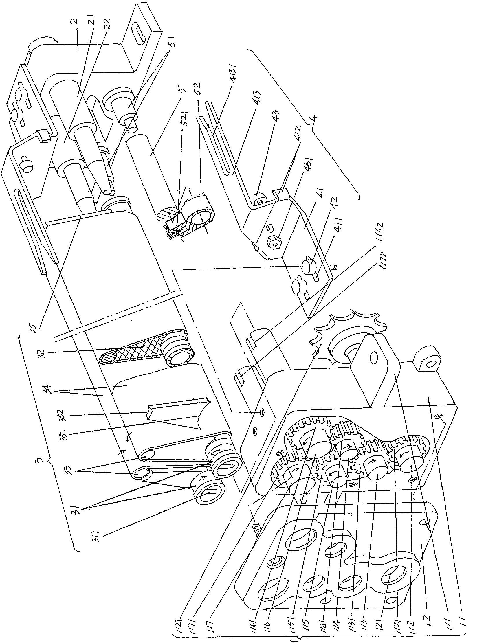
[0021] Please refer to figure 1 A preferred but not absolutely limited power transmission device 1 is given, which is composed of a gear box 11 and a box cover 12. The box cover 12 is fixed to the opening or the box mouth of the gear box 11 by a set of fixing screws. The box cover 12 is provided with shaft holes 121 equal to the number of the shafts mentioned below. The figure shows a total of six shaft holes 121, indicating that six shafts can be pivoted by means of the shaft holes 121. On the box body of the gear box 11, one end of the driving shaft 112, the transition shaft 113, the first and second transmission shafts 114, 115, the first and second roller driving shafts 116, 117 are pivoted from bottom to top. The other end of the shaft, the left end shown in the figure, is pivoted on the aforementioned corresponding shaft hole 121. The drive shaft 112, the transition shaft 113, the first and second drive shafts 114, 115, and the first and second roller drive shafts 116, 117 ...


PUM


Abstract

The invention relates to an accessory roller apparatus for a computer flat knitting machine comprising a power transmission, a bracket and a pair of fabric traction devices; wherein the power transmission comprises a gear box and a box cover; the fabric traction devices comprises a roller, a transition bar bracing piece arranged on the roller, a transition bar arranged on the top part of the transition bar bracing piece and pinch fabric sleeves enveloping the roller, the transition bar bracing piece and the transition bar. The accessory roller apparatus is characterized in that the fabric traction device also comprises two pairs of limit plates and each pair of the limit plates is corresponding to both ends of the transition bar bracing piece; wherein the lower end of the limit plate is supported on the roller and the upper end is supported on the transition bar; anti-oscillatory devices are arranged on both the top parts of the gear box and the bracket and are corresponding to both top ends of the pinch fabric sleeve. The accessory roller apparatus for the computer flat knitting machine has the advantages of simple structure, low power transfer loss, elimination of left and right play of the transition bar bracing as well as irregular play of the woven fabric.

Description

Technical field [0001] The invention belongs to the technical field of knitting machinery, and specifically relates to a secondary roller mechanism of a computerized flat knitting machine. Background technique [0002] As the industry knows, it is necessary to configure the auxiliary roller mechanism on the flat knitting machine, especially the computer flat knitting machine. The specific position of the auxiliary roller mechanism on the flat knitting machine corresponds to a pair of needles that are roughly distributed in a figure eight shape. The bottom of the bed, and as close as possible to the mouth of the cylinder, which means that its position is required to be higher. For this reason, the industry also calls the secondary roller mechanism a high roller mechanism. [0003] The responsibility of the auxiliary roller mechanism is to pull down the knitting mechanism of the flat knitting machine in the knitting process after the knitted fabric is held in a holding state, so as...

Claims


Application Information

Patent Timeline
Patent Type & Authority Patents(China)
IPC IPC(8): D04B15/90D04B15/96
Inventor 金永良赵建生
Owner JIANGSU JINLONG TECHNOLOGY CO LTD
Why Eureka
Try Eureka