Method and equipment for solid-liquid separation

A solid-liquid separation and equipment technology, which is applied in the field of solid-liquid separation, can solve the problems that affect the improvement of the filter cake degree of the belt filter press, reduce the filtration efficiency, and the wear of the filter belt, so as to improve the pressing dehydration efficiency and high dehydration efficiency , the effect of a reasonable structure

Inactive Publication Date: 2009-11-11
ZHEJIANG HUAZHANG TECH
View PDF6 Cites 1 Cited by
  • Summary
  • Abstract
  • Description
  • Claims
  • Application Information

AI Technical Summary

Problems solved by technology

The belt filter press with this structure has the following defects: 1. The pressing rollers are arranged from large to small along the traveling direction of the filter belt, and the pressing pressure gradually increases. When the upper and lower filter belts are running under high tension, the filter belt is worn Serious; if one filter belt runs with high tension and the other runs with low tension, the low tension filter belt will loosen and cannot operate normally
In order to avoid the wear or loosening of the filter belt, the existing technology can only choose a lower tension operation, which affects the improvement of the filter cake degree of the belt filter press
2. The continuous upper and lower filter belts are used in the pressing area from the feeding to the discharging, which makes it difficult to maintain the optimal match among the pressing pressure, filter belt pore size and filter cake properties
If the pore size of the filter belt in the low-pressure zone is too small, the filtration efficiency will be reduced, and a larger pore size should be used; if the filter belt pore size is too large in the high-pressure zone, the filter cake will penetrate the filter belt, so a smaller pore size should be used. The existing technology cannot take into account both high and low pressure. It is difficult to maintain the best operating condition of the belt filter press due to the requirements of the region for the filter belt
3. Both the upper and lower filter belts use dehydration filter belts. When the press rollers are arranged horizontally, a large part of the liquid separated by the upper filter belt is sucked back by the filter cake; The pressurization effect is not good, and the solid-liquid separation is not ideal
4. The existing technology cannot realize the separate adjustment of the tension of the press rollers in the early stage of pressing and in the later stage of pressing. In order to avoid the phenomenon of mud running at both ends caused by excessive pressure when the solid content is relatively low in the early stage of pressing, it can only be operated at low tension; and low tension When the solid content is high in the later stage of pressing, no water can be squeezed out due to the low pressure, and the dehydration effect is poor, so that the solid-liquid separation efficiency of the whole equipment is not high.
However, due to the material of the steel rope pressurized belt itself, its folding resistance is poor, and its service life is short, generally no more than 2000 hours, which limits the rapid development of this technology

Method used


Image

  • Method and equipment for solid-liquid separation
  • Method and equipment for solid-liquid separation
  • Method and equipment for solid-liquid separation

Examples


Embodiment 1

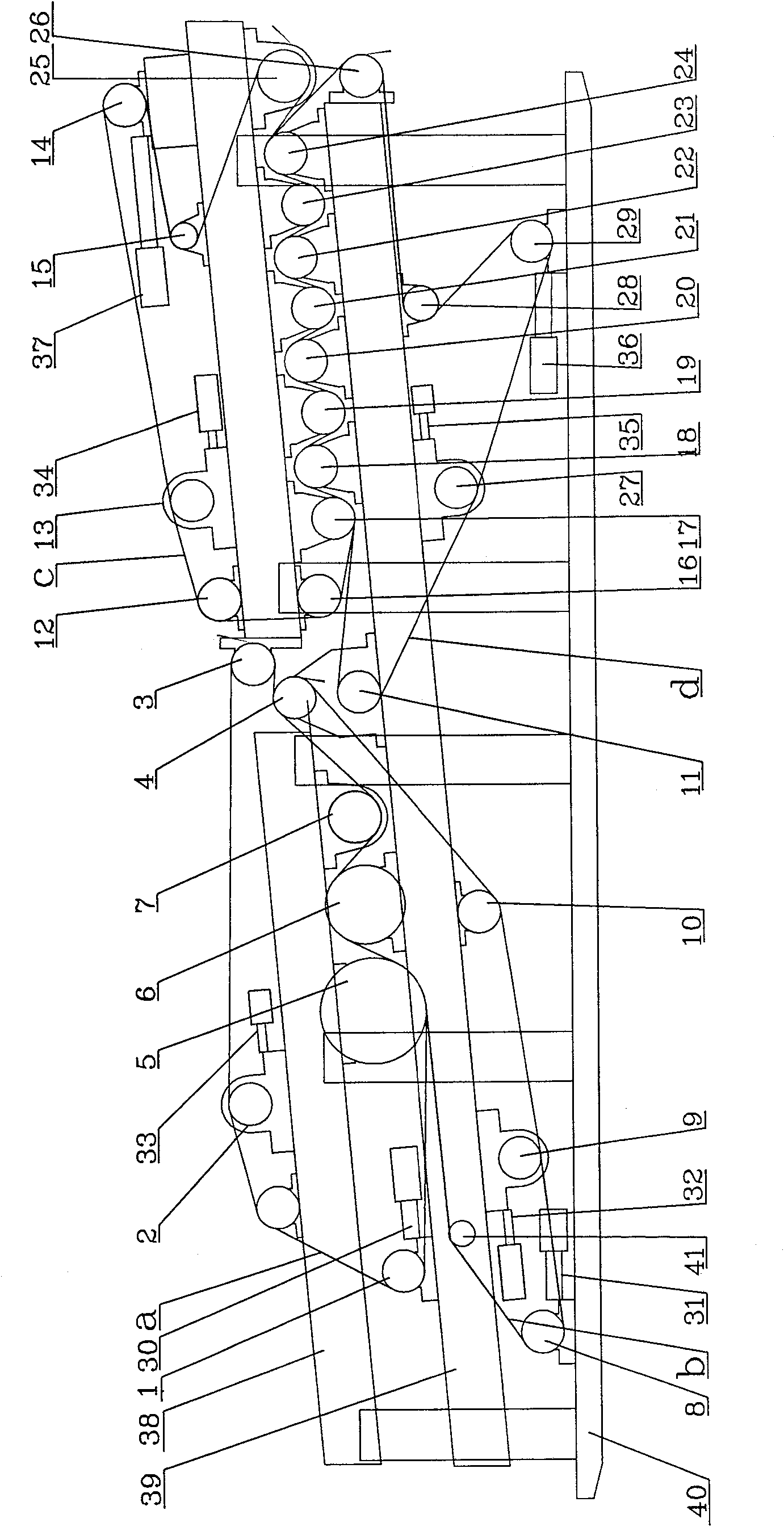
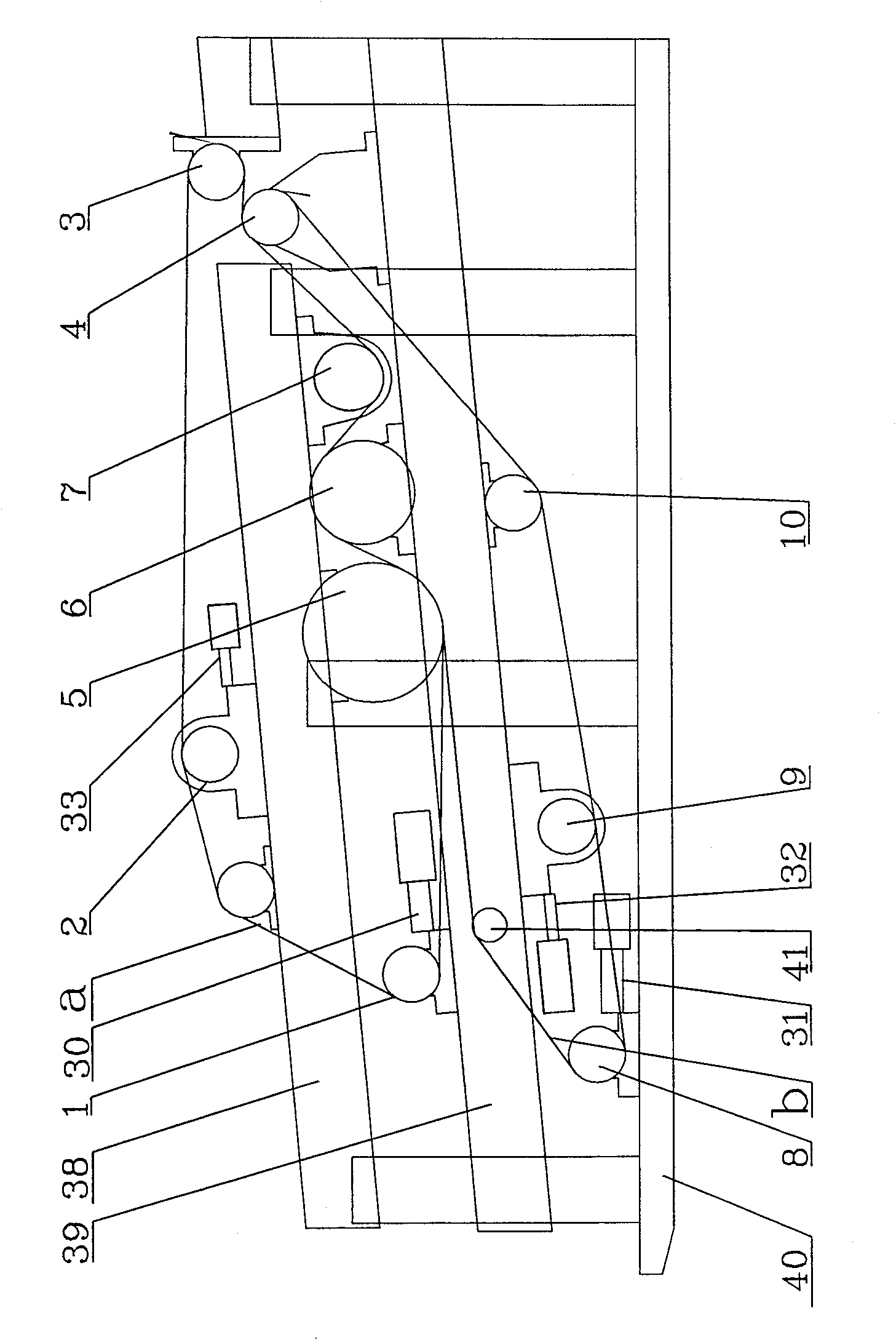
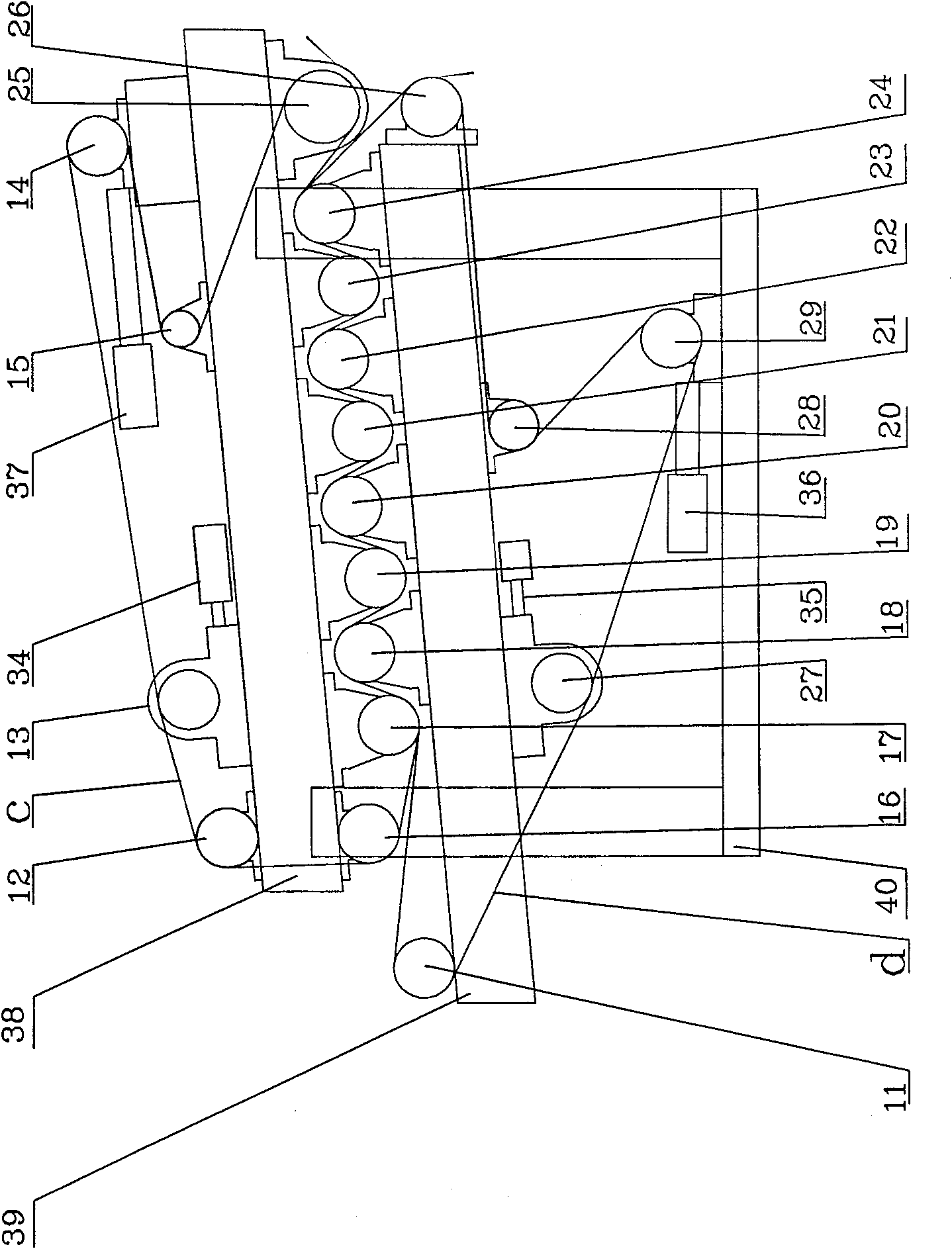
[0036] The solid-liquid separation equipment in this embodiment is equipped with two press dehydration zones, low pressure and high pressure. For the structure of the press dehydration zone in the embodiment, see Figure 1-3 .

[0037] see figure 1 , 2 , the upper pressure belt a in the low-pressure press area of ​​this embodiment wraps around the idler roller 1, the correction roller 2, the idler roller 3, the main drive roller 4, the idler roller 7, the press roller 6, and the idler roller 5; the lower filter belt b wraps Idler roller 8, idler roller 5, press roller 6, idler roller 7, main drive roller 4, idler roller 10, deviation correction roller 9. As shown in the figure, idler rollers 1, 3, 5, 7, 8, 10, correction rollers 2, 9, main drive roller 4, and press roller 6 are installed on the upper frame 38, the lower frame 39 and the bottom of the frame respectively. Rack 40. The upper pressure belt a wrapped around the outer bottom of the idler 1 and the lower filter ...

Embodiment 2

[0051] The solid-liquid separation equipment in this embodiment is equipped with three press dehydration zones of low pressure, medium pressure and high pressure. For the structure of the press dehydration zone in the embodiment, see Figure 4 , 5 .

[0052] The structure of the low pressure press zone of this embodiment is the same as that of the low pressure press zone of embodiment 1; the structure of the middle press zone is the same as that of the high pressure press zone of embodiment 1. The structure of the high pressure press section see Figure 5 , the upper pressure belt e wraps around the idler roller 42, the correction roller 43, the tension roller 47, the idler roller 45, the main drive roller 54, the press roller 53, the idler roller 52, the press roller 51, the idler roller 50, and the idler roller 49, The lower filter belt f wraps around the idler roller 48, the idler roller 50, the squeeze roller 51, the idler roller 52, the squeeze roller 53, the idler roll...


PUM


Abstract

The invention discloses a solid-liquid separation method and equipment specially used for various organic and inorganic microparticle suspensions or solid-liquid mixtures such as industrial waste water, paper pulp, domestic sludge, and oily sludge. In this method, when the material to be separated enters the press dehydration after pre-treatment, concentration and pre-dehydration, an independent filter belt is used to carry out two-stage or more press pressure from low to high continuous belt press dehydration. The press dehydration zone of the equipment includes two or more press zones equipped with independent filter belts, and the pressing pressure is from low to high. The feed ports of the subsequent pressing areas face the discharge ends of the previous pressing areas respectively. The invention overcomes the defects of the prior art, and has the advantages of being scientific and practical, reasonable in structure, flexible in adjustment, and high in dehydration efficiency. The solid content of the dehydrated material is increased to more than 40% by the solid-liquid separation of the invention, reaching the semi-cured level.

Description

technical field [0001] The present invention relates to a solid-liquid separation method and equipment, in particular to a combined, single-unit separation method for various organic and inorganic microparticle suspensions or solid-liquid mixtures, such as industrial waste water, pulp, domestic sludge, oily sludge, etc. Separation methods and equipment for pressing and semi-drying solid-liquid. Background technique [0002] Water treatment plants, paper mills, food processing plants, chemical plants, and farms will produce a large amount of microparticle suspensions or solid-liquid mixtures, including semi-finished products from some manufacturers, or waste such as sewage and sludge. The solid content of these materials is only 3-5%, and the liquid content is high and the volume is large. According to relevant records, if the moisture content of sludge is reduced from 95% to 80%, its volume will be reduced by 75%; if it is reduced from 80% to 50%, its volume will be reduced...

Claims


Application Information

Patent Timeline
Patent Type & Authority Patents(China)
IPC IPC(8): B01D33/04B30B9/24
Inventor 唐志超沈海勇钟天平程剑冰余真德李小整胡杭滨黄柏林毛怡红胡佳蓓
Owner ZHEJIANG HUAZHANG TECH
Why Eureka
Try Eureka