Wide-frequency-band double-way-band incongruous medium transmission wire

A technology of heterotropic media and transmission lines, which is applied in the direction of waveguides, circuits, electrical components, etc., can solve the problems of large electrical size, difficult processing, and high cost of anisotropic media transmission lines, and achieve good application prospects, low cost, and low loss.

Inactive Publication Date: 2009-12-02
HARBIN INST OF TECH
View PDF3 Cites 0 Cited by
  • Summary
  • Abstract
  • Description
  • Claims
  • Application Information

AI Technical Summary

Problems solved by technology

[0004] In order to solve the problems of large electrical size, difficult processing, high cost and narrow bandwidth of existing heterotropic dielectric transmission lines, the present invention provides a broadband dual-pass band heterotropic dielectric transmission line

Method used


Image

  • Wide-frequency-band double-way-band incongruous medium transmission wire
  • Wide-frequency-band double-way-band incongruous medium transmission wire
  • Wide-frequency-band double-way-band incongruous medium transmission wire

Examples


specific Embodiment approach 1

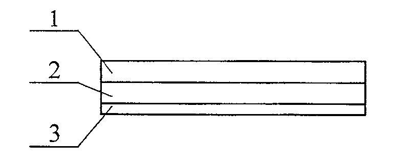
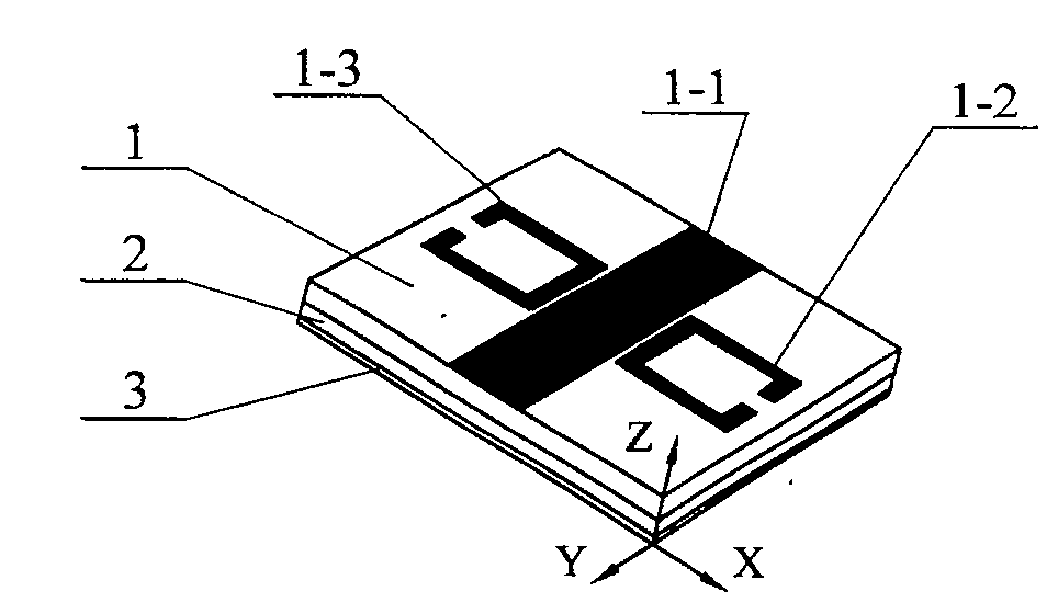
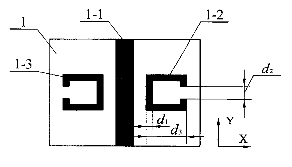
[0008] Specific implementation mode one: see Figure 1 to Figure 5 , the broadband dual-pass band heterotropic dielectric transmission line of this specific embodiment is composed of a plurality of heterotropic dielectric units, and each heterotropic dielectric unit is composed of a first layer of dielectric board 1, a second layer of dielectric board 2 and a bottom metal foil 3 stamped together to form a figure 2 shown; as image 3 As shown, a metal strip 1-1 is etched in the middle of the upper surface of the first dielectric board 1 along the Y direction, and a metal strip 1-1 is etched in the middle of the upper surface of the first dielectric board 1 along the X direction. A square split metal ring 1-3 and a second square split metal ring 1-2, the shape of the first square split metal ring 1-3 and the second square split metal ring 1-2 is a square metal ring A symmetrical shape is left after removing a part of one side, the shape of the first square split metal ring, t...

specific Embodiment approach 2

[0010] Specific implementation mode two: the difference between this specific implementation mode and specific implementation mode one is: as image 3 As shown, the openings of the first square split metal ring 1-3 and the second square split metal ring 1-2 face away from the metal strip 1-1; Figure 4 As shown, the openings of the third square split metal ring 2-1 and the fourth square split metal ring 2-2 are opposite. Other components and connections are the same as those in the first embodiment.


PUM


Abstract

A wide-band double-pass-band heterotropic medium transmission line relates to the technical field of heterotropic mediums, and solves the problems of the existing heterotropic medium transmission lines such as large electrical size, difficult processing, high cost and narrow bandwidth. The anisotropic dielectric transmission line of the present invention is composed of a plurality of anisotropic dielectric units connected in series, and in each anisotropic dielectric unit, a metal strip (1- 1), the first square open metal ring (1-3) and the second square open metal ring (1-2) are arranged symmetrically with the metal strip (1-1) as the symmetrical axis; the second layer of dielectric plate (2) A third square open metal ring (2-1) and a fourth square open metal ring (2-2) are etched in the middle of the upper surface along the X direction; the bottom metal foil (3) is provided with two identical and interconnected square through hole. The anisotropic dielectric transmission line of the invention has the characteristics of double-pass frequency bands, small unit volume, easy processing, low cost, wide bandwidth and low loss.

Description

technical field [0001] The invention relates to the technical field of heterotropic media. Background technique [0002] Anisotropic medium is a new type of artificial electromagnetic medium with periodic structure that appeared in the late 1990s. It has both negative permittivity and negative magnetic permeability, resulting in the electric field E of the electromagnetic wave propagating in the medium, The magnetic field H and the wave vector k form a left-handed system, instead of following the right-handed rule of conventional media, so it is also called an anisotropic medium. The prototype of the concept of heterotropic medium needs to be traced back to the 1960s. Veselago, a former Soviet physicist, studied it theoretically for the first time, and predicted that the heterotropic medium has a series of unconventional electromagnetic properties, including: left-handed characteristics, Negative refraction characteristics, inverse Doppler effect, inverse Cerenkov radiation...

Claims


Application Information

Patent Timeline
Patent Type & Authority Patents(China)
IPC IPC(8): H01P3/00
Inventor 吴群孟繁义武明峰傅佳辉王海龙金博识
Owner HARBIN INST OF TECH
Why Eureka
Try Eureka