Second confocal measuring method and apparatus based on movable phase interfere

A technology of phase-shifting interference and measurement methods, which is applied in the field of ultra-precision non-contact fast, large-scale scanning measurement, and can solve the problems of measuring surface reflectivity differences, inability to directly measure the step height, etc., and achieve the effect of a large range.

Inactive Publication Date: 2009-12-09
HARBIN INST OF TECH
View PDF11 Cites 0 Cited by
  • Summary
  • Abstract
  • Description
  • Claims
  • Application Information

AI Technical Summary

Problems solved by technology

Its basic idea was proposed by M.Minsky in 1957 and obtained a US patent in 1961. Its basic idea is to suppress stray light by introducing a pinhole detector and generate axial tomography capabilities. The shortcomings of this technology The reason is that the measurement sensitivity of the axial response signal is not high near the quasi-focus area of ​​the measurement surface, so it is only suitable for defocus displacement measurement
The essence of interferometry is to convert displacement changes into phase changes to achieve microstructure and micro-displacement measurement. This type of measurement technology well solves the problem of the influence of the measurement surface reflectivity and surface tilt on the measurement results. However, due to the phase measurement value solution has Periodicity, so this type of measurement method cannot be directly used for step height measurement, only relative displacement changes can be obtained, and it cannot be directly used for absolute displacement measurement
[0006] The invention provides a secondary confocal measurement method and device based on phase-shifting interference, which uses the axial tomography of the confocal detector to obtain phase information in two confocal states through two phase-shifting interferences, thereby realizing Analytical solution of defocus displacement, the purpose of the present invention is to overcome the shortcomings of traditional confocal measurement technology that is susceptible to the difference in the reflectivity of the measurement surface, the inclination of the measurement workpiece and the change of the surface profile, and the interferometric phase solution periodicity, which cannot be directly used for steps Insufficient measurement

Method used


Image

  • Second confocal measuring method and apparatus based on movable phase interfere
  • Second confocal measuring method and apparatus based on movable phase interfere
  • Second confocal measuring method and apparatus based on movable phase interfere

Examples


Embodiment Construction

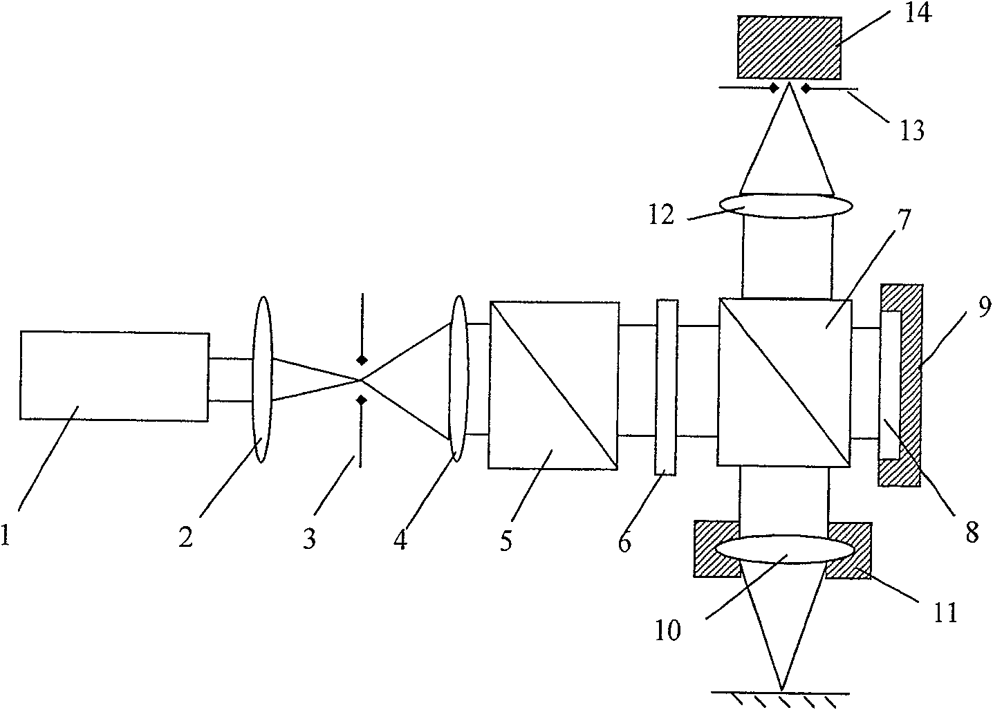
[0030] Such as figure 1 As shown, the present invention provides a secondary confocal measurement device based on phase shifting interference including: a laser 1; a collimating and focusing objective lens 2; a first pinhole 3; a collimating beam expanding objective lens 4; A wave plate 6; a beam splitter 7; a mirror 8; a first micro-driver 9; a detection focusing objective lens 10; a second micro-driver 11; a collecting objective lens 12; a second pinhole 13;

[0031] Concrete implementation steps of the present invention:

[0032] In the first step, in the first confocal state, the phase of the measurement light relative to the reference light is calculated

[0033] Such as figure 1As shown, the laser 1 emits a linearly polarized light beam, which becomes an approximate ideal plane wave after passing through the collimating beam expander lens group formed by the collimating focusing objective lens 2, the first pinhole 3, and the collimating beam expanding objective lens 4;...


PUM


Abstract

The invention discloses a secondary confocal measurement method and device based on phase-shifting interference. In the device, a laser emits a linearly polarized beam, which becomes an approximate ideal plane wave after passing through a collimating beam expander group; After one-half of the wave plate, it becomes a circularly polarized beam; it is divided into two beams by the beam splitter, the first beam is transmitted by the beam splitter, reflected by the mirror, reflected by the beam splitter, and converged by the second pinhole and detected by the collecting objective lens. A point detector composed of detectors; the second beam of light is reflected by the beam splitter, converges on the measurement surface through the detection focusing objective lens and the beam splitter, is reflected on the measurement surface, passes through the detection focusing objective lens, and converges on the point detector through the collecting objective lens; the first The micro-driver is used to drive the mirror to change the phase difference between the reference light and the measurement light to realize phase-shifting interference; the initial position of the measurement point is the first confocal state. The invention also discloses a secondary confocal measurement method based on phase-shifting interference.

Description

technical field [0001] The invention belongs to the field of ultra-precision measurement, and is an ultra-precise non-contact measuring device for measuring three-dimensional microstructures, microsteps, microgroove line width, depth and surface shape in microstructured optical elements, microstructured mechanical elements, and integrated circuit elements. Fast, large-scale scanning measurement method and device. Background technique [0002] Confocal scanning measurement is one of the important technical means to measure three-dimensional microstructure, micro-step, micro-groove line width, depth and surface shape in the fields of micro-optics, micro-mechanics and micro-electronics. Its basic idea was proposed by M.Minsky in 1957 and obtained a US patent in 1961. Its basic idea is to suppress stray light by introducing a pinhole detector and generate axial tomography capabilities. The shortcomings of this technology The reason is that the measurement sensitivity of the axi...

Claims


Application Information

Patent Timeline
Patent Type & Authority Patents(China)
IPC IPC(8): G01B9/02G01B11/00G01B11/02G01B11/22G01B11/24
Inventor 谭久彬刘俭
Owner HARBIN INST OF TECH
Why Eureka
Try Eureka