
Test case generating method based on relationship

A test case generation and test case technology, applied in the direction of software testing/debugging, program control devices, etc., can solve the problems of insufficient consideration of the mutual influence of factors, redundant testing of test cases, and inability to refer to the design of relational use cases, etc. Scaling, improving efficiency and quality

Inactive Publication Date: 2009-12-09
孙影 +4
View PDF6 Cites 0 Cited by
  • Summary
  • Abstract
  • Description
  • Claims
  • Application Information

AI Technical Summary

Problems solved by technology

[0007] (2) Existing software test case design method
[0028] The test cases designed by the uniform test case design method take values ​​for each level of each factor, but the interaction between factors is not considered enough. For example, X1 and X2 are a pair of keywords, then X1 and X2 should be X2 takes repeated values ​​for testing, and the uniform use case design method cannot do this
[0029] Both the orthogonal test case design method and the uniform test case design method are derived from the experimental design. They are experimental methods designed to determine the influence of the relationship between various factors on the results. In the software test case design, the relationship between the various factors The interrelationship among them has been determined, and there are many factors that are independent of each other and do not affect each other. At this time, the above-mentioned method is used for test case design, and multiple cross-tests are still performed on these mutually independent factors, resulting in a large number of redundant test cases. Excessive or missing tests increase the cost and risk of testing
[0030] Each function in the software is often interrelated, and the orthogonal test case design method and the uniform test case design method cannot design use cases for the reference relationship between functions.

Method used


Image

  • Test case generating method based on relationship
  • Test case generating method based on relationship
  • Test case generating method based on relationship

Examples


Embodiment Construction

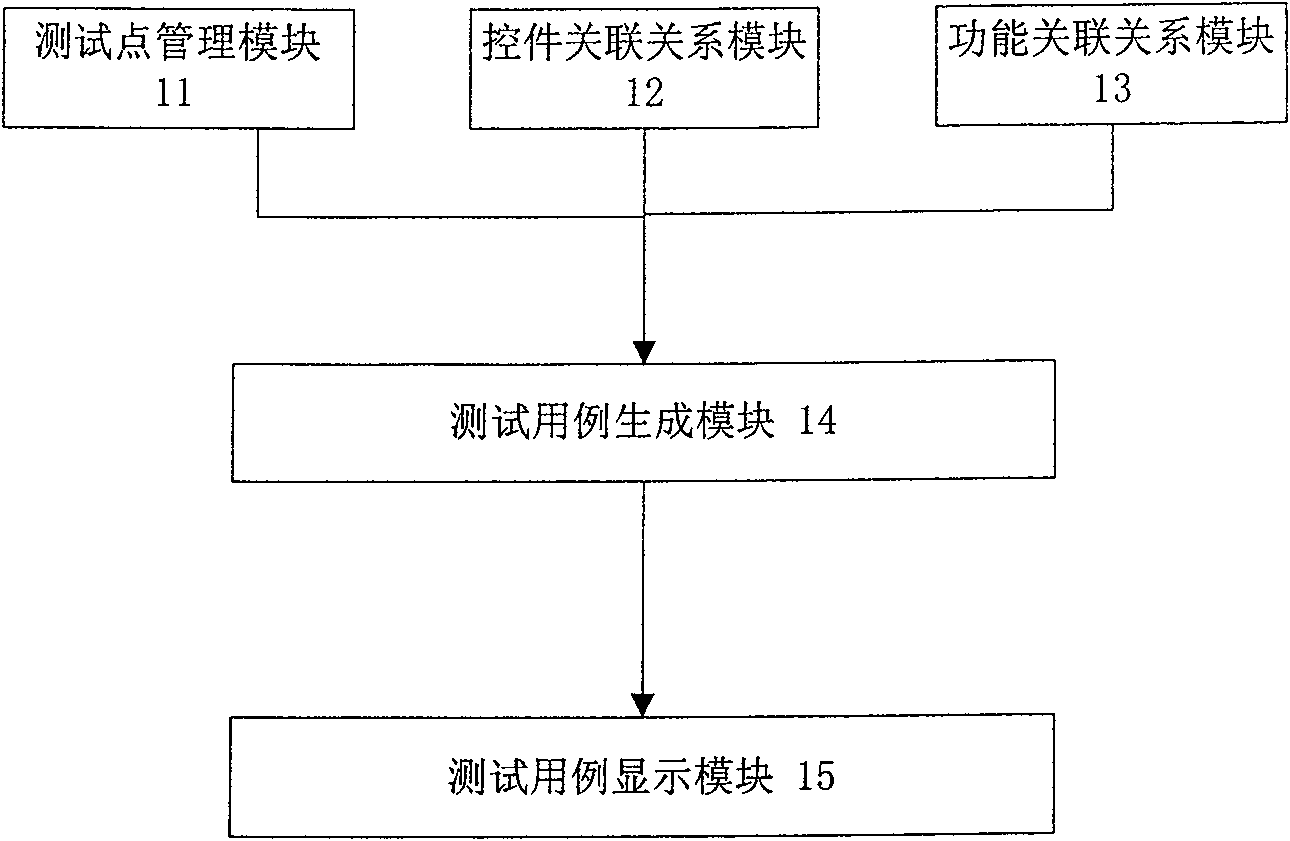
[0051] At first, illustrate the key steps of the inventive method, specifically include:

[0052] A. Design key test points for GUI dialog boxes, buttons, similar functions and associated controls;

[0053] B. Determine the control relationship diagram according to the requirements and detailed design, and design test cases according to the independent relationship and association relationship between controls;

[0054] C. Determine the functional relationship diagram according to the reference relationship between functions, and design test cases according to the functional relationship diagram;

[0055] Step A further includes:

[0056] A1. Optimize the test points of each control based on the experience of boundary value testing, equivalence class testing and various abnormal testing;

[0057] A2. Make the test points of each control into a template, which is convenient for future reference and expansion.

[0058] Step B further includes:

[0059] B1. Determine the cont...


PUM


Abstract

The invention relates to a method for generating test cases based on relationships, comprising: selecting a test point for each control in a graphical user interface to be tested according to a category; selecting each control according to the principle that all levels of each factor are obtained value and fully combine and merge the associated controls; generate test cases according to the reference relationship of the function to be tested and the use case template; merge the above test cases to generate all test cases of the function to be tested. This method combines boundary value testing and equivalence class testing to carry out rigorous, standardized and comprehensive test point design for common controls in interface testing, and then solidify the test design points of each type of control into a set of test case generation specifications , easy to reference and expand, and then through the analysis of control correlation and function correlation, use the control relationship diagram and function relationship diagram to design use cases, so that the selection of test case input values ​​is more targeted, thus greatly improving GUI testing. Efficiency and quality of design.

Description

technical field [0001] The invention relates to a software test case, in particular to a method for generating a test case based on a control relationship and a function relationship in a graphical user interface GUI. Background technique [0002] (1) Software testing [0003] Software testing in a broad sense includes the testing and verification of software to meet requirements at each stage of the software life cycle, such as whether the product meets the needs of users, product performance, ease of use, etc. [0004] Software testing in a narrow sense can be summarized as a test on the model: Y=F(X1, X2, ..., Xn), where X1, X2, ..., Xn are input variables, and F is the pair of variables X1, X2, ..., a transformation of Xn, Y is the desired result. Various test case design methods are actually different designs of the function F. [0005] In software, many variables may have infinitely many values, and due to resource constraints and engineering needs, software testing...

Claims


Application Information

Patent Timeline
Patent Type & Authority Patents(China)
IPC IPC(8): G06F9/44G06F11/36
Inventor 吕俊廷
Owner 孙影
Learn More