
Polarization rotation switch
A polarization rotation and switching technology, which is applied in the optical field, can solve the problems such as little improvement, achieve the effect of increasing the switching speed, increasing the jitter speed, and solving the problem of smearing
- Summary
- Abstract
- Description
- Claims
- Application Information
AI Technical Summary
Problems solved by technology
Method used
Image

Examples
Embodiment Construction
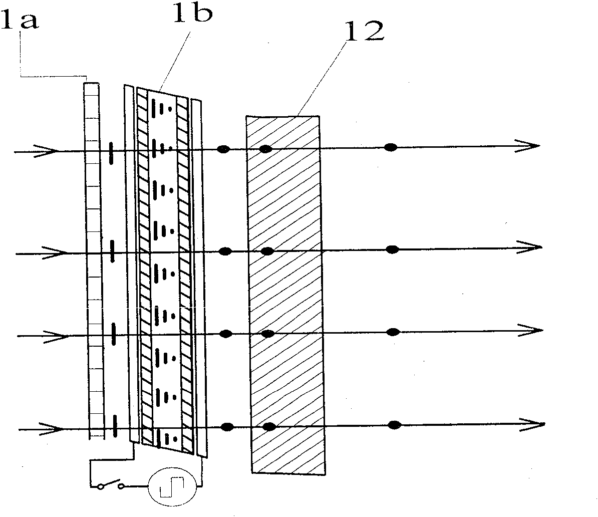
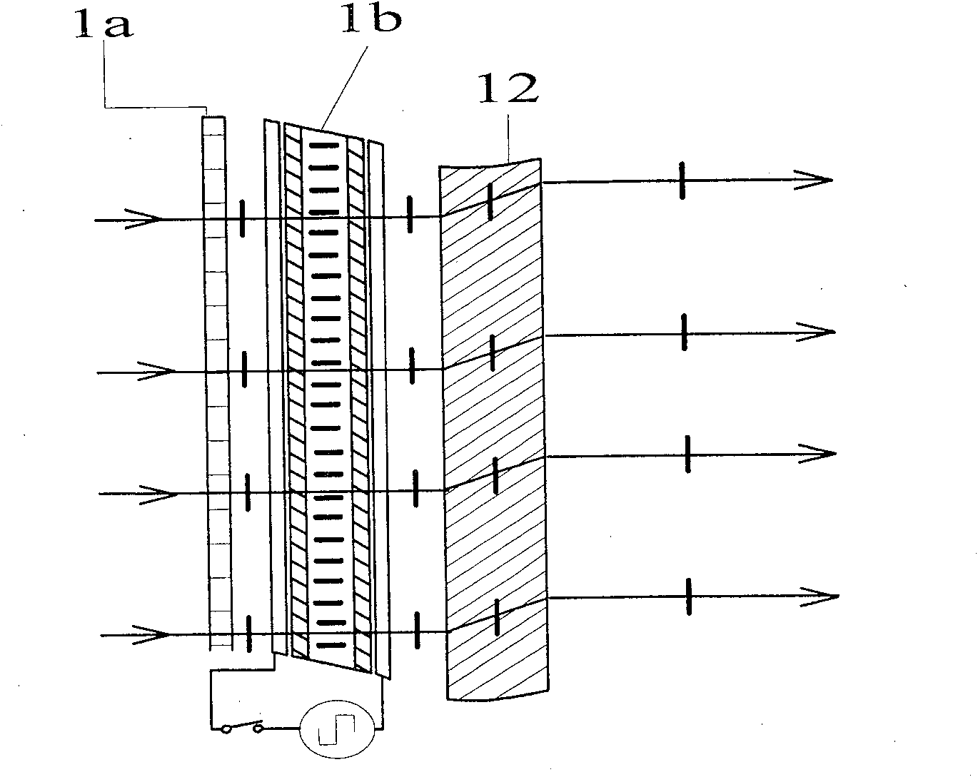
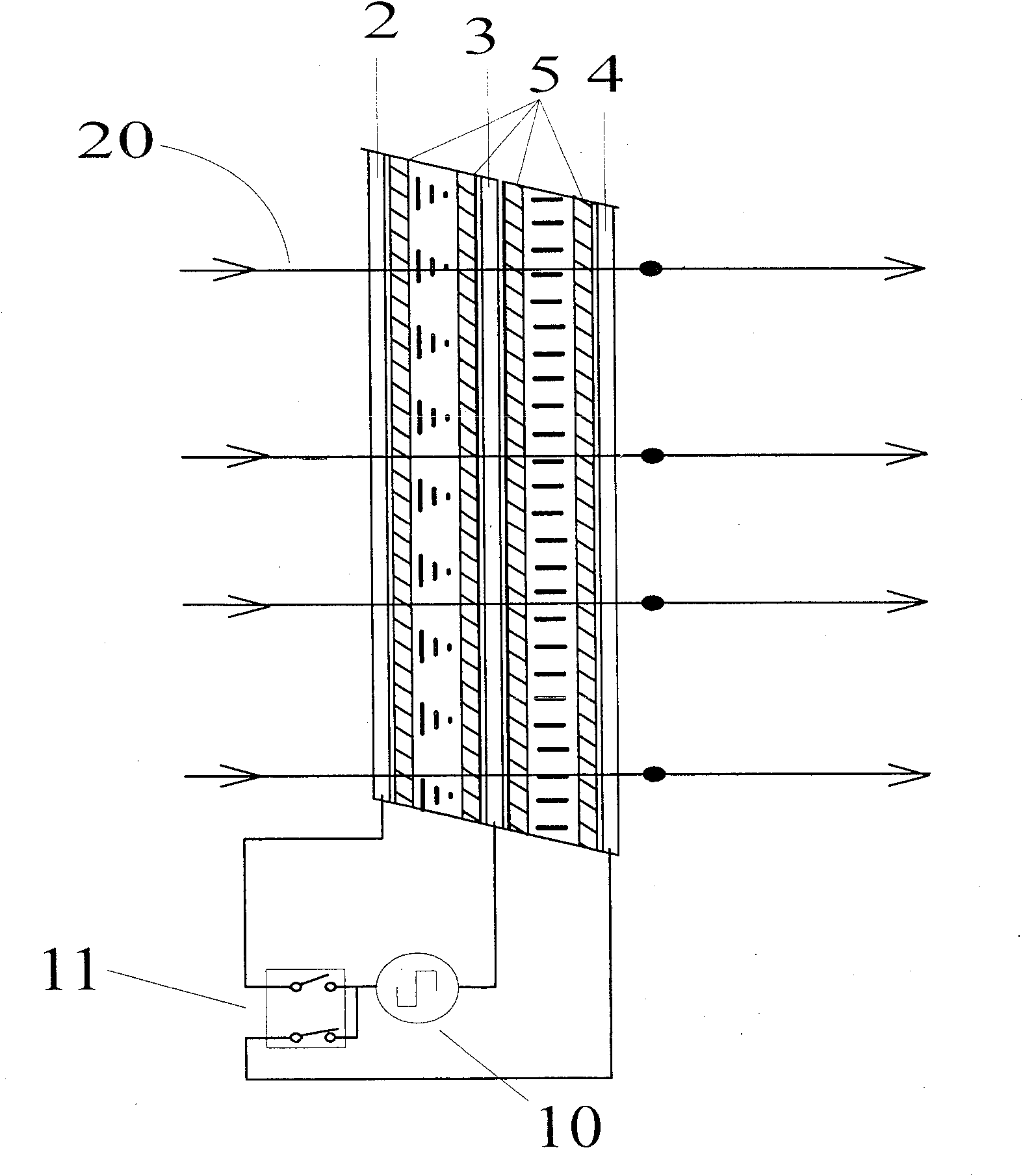
[0020] see Figure 2a , the figure is a schematic diagram of the structure of the polarization rotary switch, reference numerals 2, 3, 4 respectively represent three transparent electrodes, reference numeral 5 represents four alignment layers, respectively the first, second, third and the first Four alignment layers; the first alignment layer is coated on the surface of the transparent electrode 2, the second alignment layer is coated on the first surface of the transparent electrode 3, and the third alignment layer is coated on the transparent electrode 3 opposite to the first surface The second surface of the fourth alignment layer is coated on the surface of the transparent electrode 4, between the first and second alignment layers, and between the third and fourth alignment layers are filled with nematic liquid crystal , wherein, the orientation of the first orientation layer and the orientation of the second orientation layer form an angle of 45 degrees to each other; the...
PUM
 Abstract
Description
Claims
Application Information