Compact self-ballasted fluorescent lamp and lighting apparatus

A technology of self-ballasting and fluorescent lamps, which is applied in the direction of lighting devices, components of lighting devices, cooling/heating devices of lighting devices, etc. It can solve the problems of reducing electronic components, increasing the occupied area of ​​electronic components, and making it difficult to form the appearance of light bulbs, etc. , to achieve the effect of improving installation efficiency and ensuring width

Inactive Publication Date: 2010-01-13
TOSHIBA LIGHTING & TECH CORP
View PDF11 Cites 3 Cited by
  • Summary
  • Abstract
  • Description
  • Claims
  • Application Information

AI Technical Summary

Problems solved by technology

In addition, electronic components such as smoothing capacitors with a large component height need to be mounted in a state where the lead wires are bent approximately 90° so that the longitudinal direction is along the substrate, and the height of the electronic component protruding from the substrate needs to be reduced. In this case, The area occupied by electronic components in the substrate increases, leading to an increase in the size of the substrate
[0010] In this way, only by arranging the substrate vertically, and arranging the narrow portion of the substrate and a part of the electronic components inside the cap, the lighting device cannot be efficiently accommodated inside the cap, and the miniaturization of the cover cannot be fully realized. Appearance
[0011] Furthermore, in the small self-ballasted fluorescent lamp in which the thin tube described in Patent Document 1 is arranged inside the cap, the thin tube is arranged near the front end of the large electronic component, and the component arrangement efficiency in the inner space of the cap is insufficient.
In particular, electronic components must be mounted on the substrate and cannot be in contact with the thin tube, so there is a limit to improving the effective efficiency. Naturally, the area of ​​the substrate on the side of the luminous tube becomes larger than that of the lamp head, so it is difficult to miniaturize the cover.

Method used


Image

  • Compact self-ballasted fluorescent lamp and lighting apparatus
  • Compact self-ballasted fluorescent lamp and lighting apparatus
  • Compact self-ballasted fluorescent lamp and lighting apparatus

Examples


Embodiment Construction

[0056] Hereinafter, one embodiment of the present invention will be described with reference to the drawings.

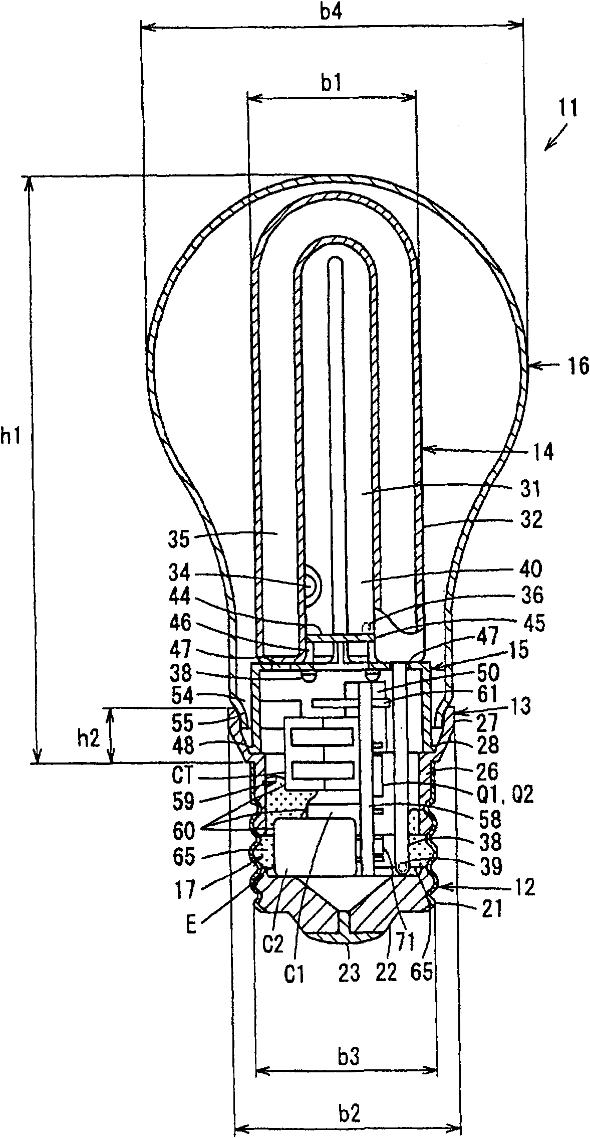
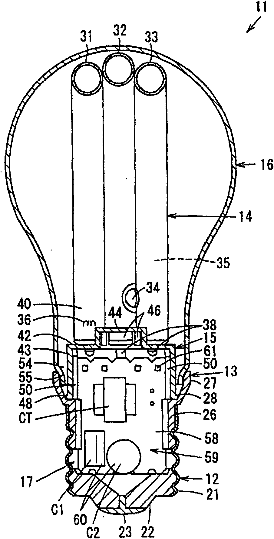
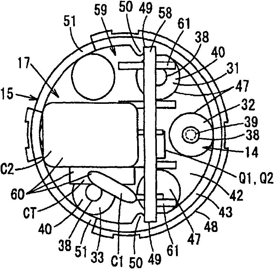
[0057] Figure 1 to Figure 8 1st Embodiment is shown. figure 1 This is a cross-sectional view of a compact self-ballasted fluorescent lamp viewed from the side where the vacuum tubes are arranged side by side. figure 2 It is a cross-sectional view when viewed from a direction intersecting the direction in which the vacuum tubes of the compact self-ballasted fluorescent lamp are arranged side by side. image 3 It is a bottom view when the cover and glass bulb of the small self-ballasted fluorescent lamp are removed and viewed from one end side of the bracket. Figure 4 It is a perspective view of a bracket for a compact self-ballasted fluorescent lamp. Figure 5 It is a perspective view of a small self-ballasted fluorescent lamp assembly, a light-emitting tube, and a base plate. Figure 6 It is a cross-sectional view showing the positional relationship between th...


PUM


Abstract

A compact self-ballasted fluorescent lamp (11) capable of providing a roughly same appearance as that of general lighting bulbs by efficiently storing a lighting device (17) on the inside of a ferrule (12) to reduce the size of a cover (13) and a lighting apparatus. The ferrule (12) is fitted to one end of the cover (13) and a light emitting tube (14) is supported on the cover (13) at the other end. Electronic parts (60) forming a lighting circuit (59) lighting the light emitting tube (14) are mounted on the substrate (58) of the lighting device (17). The substrate (58) is formed to have such a width dimension that allows the substrate to be inserted into the ferrule (12) and vertically disposed along the direction of the centerline of the ferrule (12) at a position offset from the centerline of the ferrule (12). Large electronic parts (60) among the electronic parts (60) are disposed on the surface of the substrate (58) which is more apart from the ferrule (12) than the other. Since the lighting device (17) is efficiently stored on the inside of the ferrule (12), the size of the cover (13) can be reduced and roughly the same appearance as that of the general lighting bulbs can be provided to the fluorescent lamp.

Description

technical field [0001] The present invention relates to a small self-ballasted fluorescent lamp having an arc tube and a lighting device for lighting the arc tube, and an illuminating device using the small self-ballasted fluorescent lamp. Background technique [0002] In the past, a small self-ballasted fluorescent lamp has: a light-emitting tube with a curved vacuum tube (bulb); a cover with a cap mounted on one end and a light-emitting tube supported on the other end; a lighting device housed in the cover; The other end side of the body and cover the globe of the luminous tube and the like. [0003] In addition, the following small-sized self-ballasted fluorescent lamps are known, in which the tip of a thin tube protruding from the end of the vacuum tube of the arc tube is extended inside the lamp cap, and an amalgam ( amalgam), so that the temperature at the front end of the thin tube is relatively low even when the lamp is turned on, and the mercury vapor pressure at t...

Claims


Application Information

Patent Timeline
Patent Type & Authority Patents(China)
IPC IPC(8): F21S2/00F21V23/00F21V29/00H05B41/00F21Y103/025F21Y103/37
CPCY02B20/19Y02B20/00
Inventor 久保田洋白田伸弥中村真理入江亮太小林胜之河野仁志伊藤良和志田康博
Owner TOSHIBA LIGHTING & TECH CORP
Why Eureka
Try Eureka