
Belt-breaking hydraulic protection device for belt conveyor

A belt conveyor and hydraulic protection technology, which is applied in the direction of mechanical equipment, conveyor objects, conveyor control devices, etc., can solve the problems of small contact surface, secondary broken belt, false braking, etc., and achieve strong braking force, The effect of increasing the friction factor

Inactive Publication Date: 2010-01-20
蔡瑜
View PDF4 Cites 2 Cited by
  • Summary
  • Abstract
  • Description
  • Claims
  • Application Information

AI Technical Summary

Problems solved by technology

In recent years, a variety of broken belt catchers have also appeared. In summary, their structures and control systems are all purely mechanical structures, and their braking mechanisms are mostly brake claws such as cams, eccentric wheels, and cranks. The tape that slides tightly, the contact surface with the tape is in line contact, the contact surface is small, and its friction is not enough to prevent the tape from sliding down. At the same time, the line contact is easy to cut the tape and damage the tape. In severe cases, the tape will be torn and cause secondary fracture. Belt; the catch device of the pure mechanical catcher is installed on the edge of both sides of the tape. When the tape deviates, it often rubs against the tape and damages the tape, and it is also easy to cause a load blockage.
[0004] In addition, the currently used purely mechanical broken belt catcher has a simple control system and is likely to cause false braking. For example, when the belt conveyor stops normally, the belt will continue to go up by inertia and then stop. Although a backstop or brake, but it will slide a certain distance under the action of gravity, which will cause false braking, easily damage the equipment, and cause accidents in severe cases

Method used


Image

  • Belt-breaking hydraulic protection device for belt conveyor
  • Belt-breaking hydraulic protection device for belt conveyor
  • Belt-breaking hydraulic protection device for belt conveyor

Examples


Embodiment Construction

[0026] Such as Figure 5 As shown, the upper belt (3) and lower belt (2) of the belt conveyor are installed at multiple points of the catcher device (30) and sensors (31), using the main station PLC programming controller (28) and substation (1#) , 2#, 3#, etc.) Three control modes, in which there are centralized automatic, centralized manual and decentralized local operation control.

[0027] Such as Figure 5 As shown, the sensor (31) is an incremental rotary encoder, which is characterized by no signal output in the normal phase [the running direction of the upper tape (3) normal operation], and reverse phase [the upper tape (3) slides down or conveys after the tape is broken When the machine stops normally, the upper tape (3) runs backwards for a certain distance] Collect the signal, when the encoder rotates in the reverse direction, the number of pulses per revolution (ppr) is 1000, the diameter of the encoder's measuring wheel D, the circumference of each revolution is πD...


PUM


Abstract

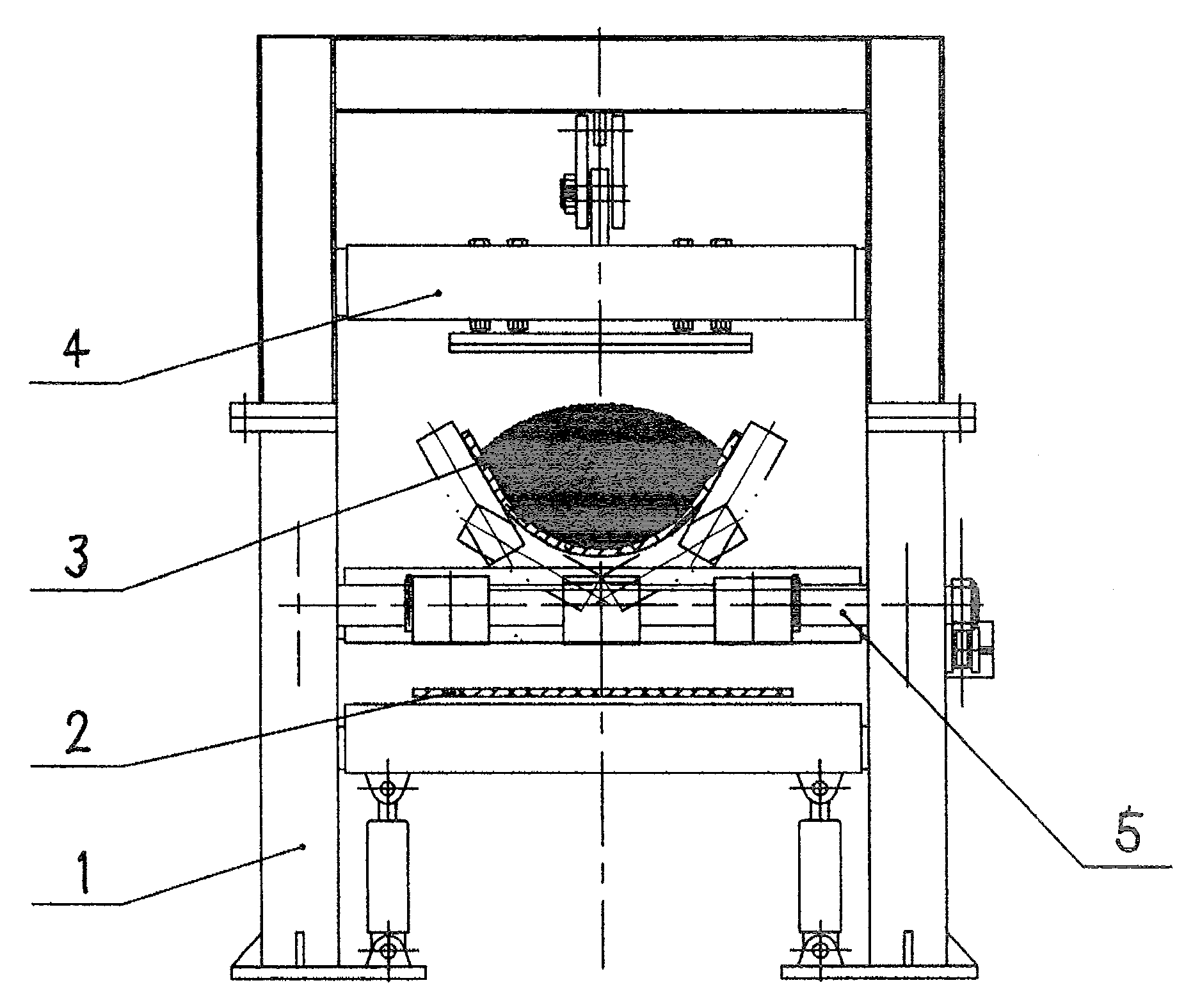
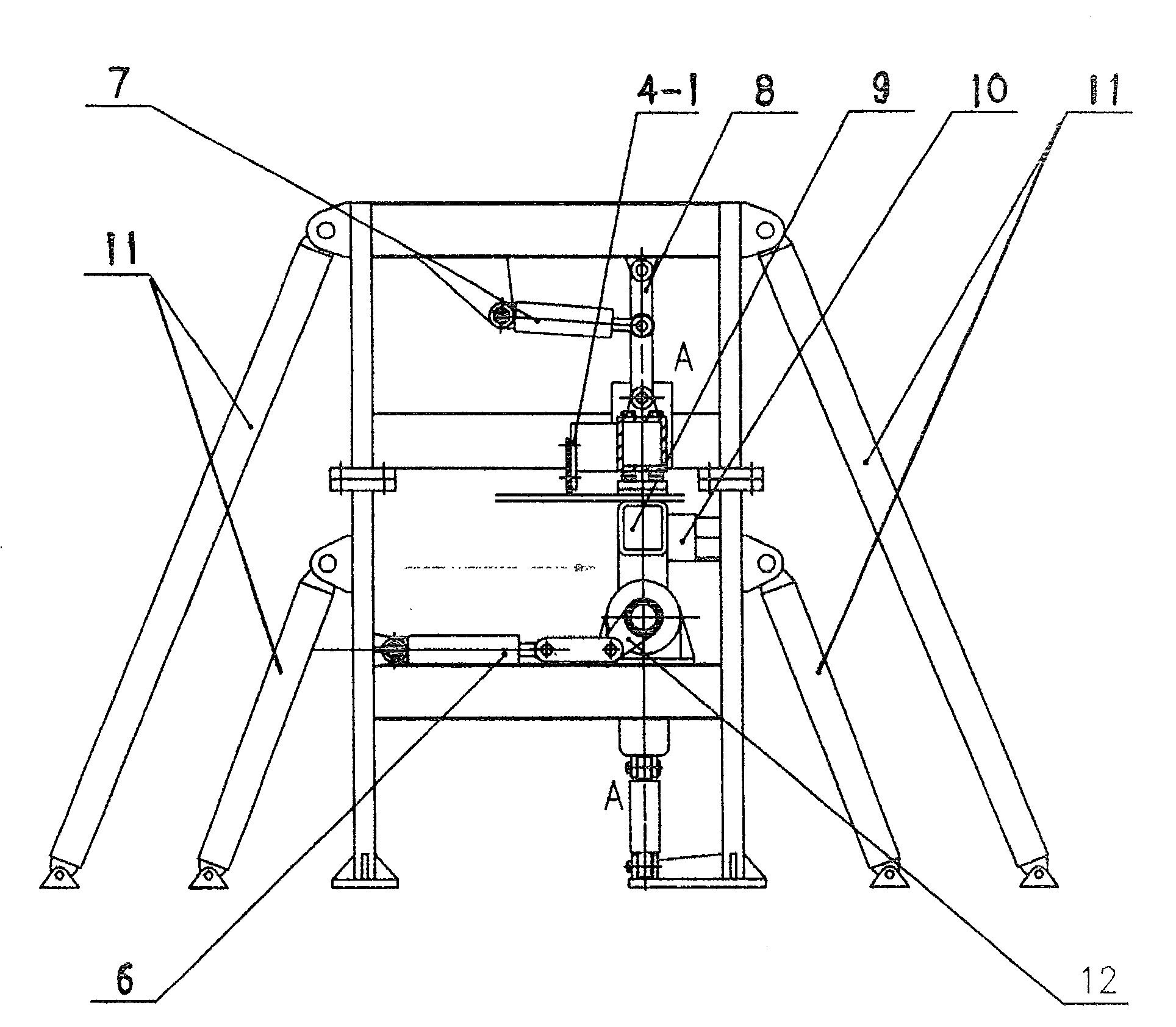
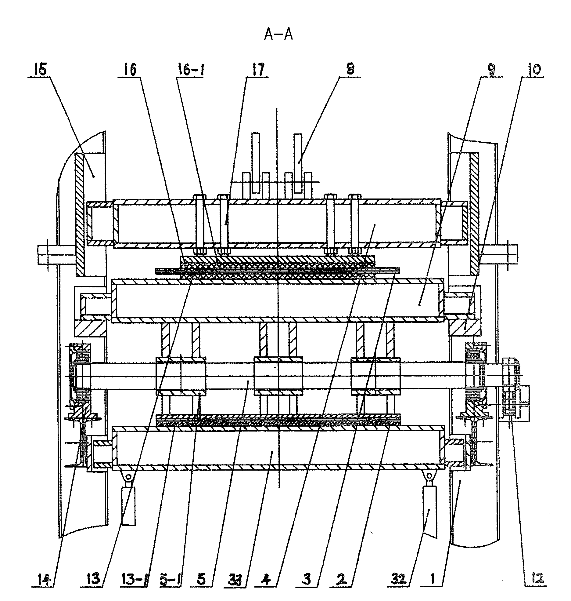
A belt breakage hydraulic protection apparatus for a belt conveyor comprises multiple belt breakage hydraulic protection apparatuses equipped on the belt conveyor, corresponding multiple sensors, a control system composed of a terminal programmable controller and multiple sub-station PLC programmable controllers via advanced communication modules, and multiple hydraulic pump stations, wherein the electric control system can acquire and judge the belt breakage signals in time and send out instructions without resulting in mistaken braking actions, the actuating mechanism of the belt breakage hydraulic protection apparatus employs the oil pumps of hydraulic pump stations and multiple airbag type accumulators to transport high pressure oil to a pull-push oil cylinder, a rotary cylinder and a lifting cylinder, the cylinders drive a top-rising beam below the upper belt to rotate and an up-pressing beam above the upper belt to move up and down to press the broken upper belt; the lifting cylinder lift a lifting beam to move up and down to press the broken lower belt. The top-rising, up-pressing beam and lifting beam have a case type structure, and friction plates are disposed between the beams and the belt contact surface to get big brake force and obvious brake effect, so that the conveyor will not generate loading stop phenomenon and abrade the belt.

Description

Technical field [0001] The present invention relates to the technical field of belt conveyors, in particular to hydraulic protection equipment for belt breakage of large-incline belt conveyors. Background technique [0002] At present, most of the belt conveyors are not equipped with broken belt catching protection devices, and usually rely on manual inspection of the tape. Due to the harsh mining environment, the maintenance is very inconvenient. The belt conveyor has a long conveying distance, especially when conveying at a large inclination. Once the belt is suddenly broken during the conveying process, if the belt cannot be braked in the shortest time, it will force the belt to stop sliding. Its destructive force is unprecedented and it will affect the equipment. And personal injury, the loss is huge. [0003] With the rapid development of the national economy, safe production and civilized production have attracted more and more attention from the government and enterprises. ...

Claims


Application Information

Patent Timeline
Patent Type & Authority Patents(China)
IPC IPC(8): B65G43/02F16P3/00
Inventor 蔡瑜
Owner 蔡瑜
Learn More