Method and apparatus for cleaning fiber material at a spinning preparation machine

A fiber material and equipment technology, applied in the field of equipment to realize the method, can solve complex continuous production, high cost, high complexity and other problems

A fiber material and equipment technology, applied in the field of equipment to realize the method, can solve complex continuous production, high cost, high complexity and other problems

CN100593044CInactive Publication Date: 2010-03-03TRUETZSCHLER GRP SE

Image

  • Method and apparatus for cleaning fiber material at a spinning preparation machine
  • Method and apparatus for cleaning fiber material at a spinning preparation machine
  • Method and apparatus for cleaning fiber material at a spinning preparation machine

Examples


Embodiment Construction

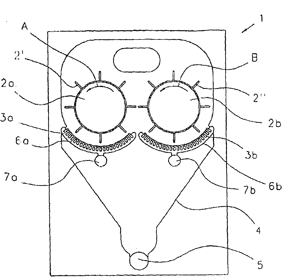
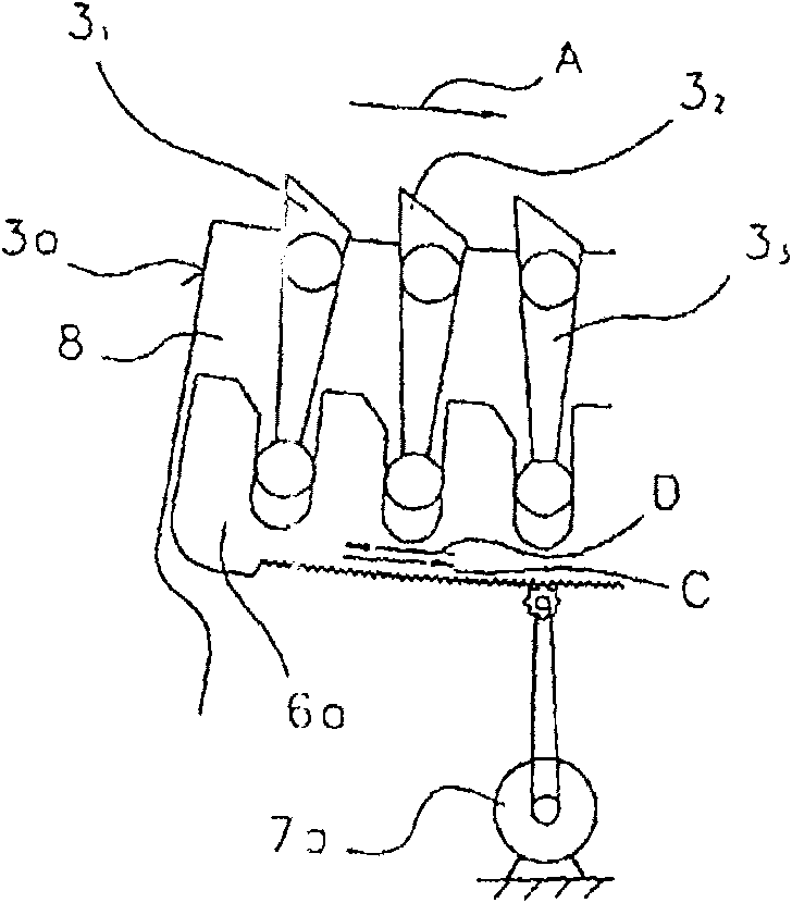
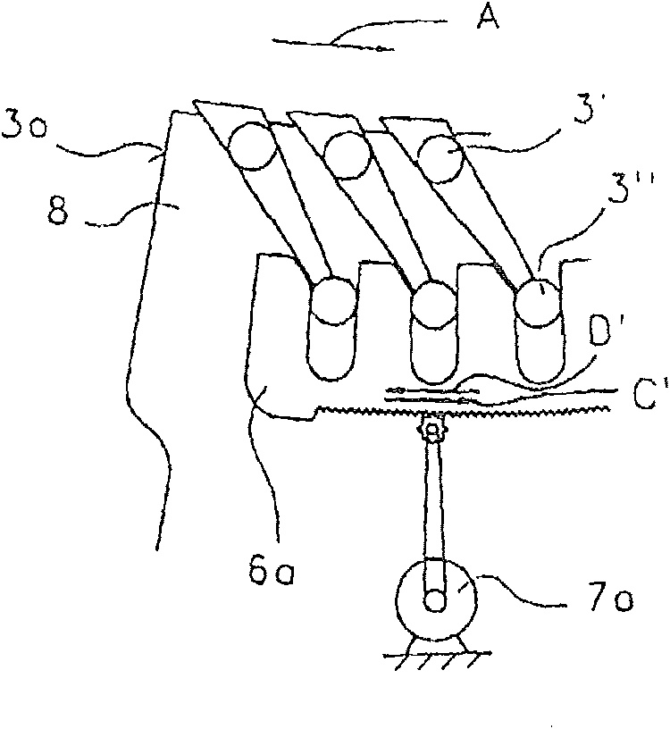
[0018] according to Figure 1a , a double-roller cleaning machine 1 (axial cleaning machine), for example a Trutzschler MAXI-FLO MFC, has two rotating uncoiler rollers 2a, 2b, beneath which are provided grids 3a, 3b with through holes. Uncoiler rollers 2a, 2b rotate counterclockwise according to arrows A, B. Figure 5 and 6 The supply of fibrous material to be cleaned and the removal of cleaned fibrous material are schematically represented. Below the grids 3a, 3b there is a waste collection device 4 which has a pneumatic waste removal line 5. Spinning wheel pins 2', 2" are fixed on the periphery of the uncoiler rollers 2a, 2b, which cause the supplied fiber batts to pass over the cleaning bars 3 of the cleaning grids 3a, 3b 1 ~3 n , the cleaning bar is arranged to surround a part of the periphery of the uncoiler rollers 2a, 2b. Grid rod (cleaning rod) 3 1 ~3 n The position of can be adjusted (see Figure 1b , 1c), thus making it possible to modify the intensity of clea...


PUM


Abstract

In a method at a spinning preparation machine, for example a cleaner, opener, carding machine or the like, for cleaning fibre material, especially cotton, an examination of the nature of the trash iscarried out, which examination is used for adjustment of at least one adjustable cleaning element, for example a separating blade, cleaning grid or the like. In order to make possible improved and undisrupted production by simple means, the optimum adjustment of the at least one cleaning element for a specific fibre batch is stored in a memory of an electronic control and regulation device and, when the same fibre batch is processed again, the optimum adjustment of the cleaning element is implemented automatically.

Description

technical field [0001] The invention relates to a method for cleaning fibrous material, in particular cotton, on spinning preparation machines such as cleaning machines, uncoilers, cards, etc., wherein a check of the nature of the waste is carried out for adjusting at least one adjustable cleaning element, such as separating Blades, cleaning grids, etc., the invention includes apparatus for implementing the method. Background technique [0002] In fact, in textile cleaning machines, for example, especially in pre-cleaning machines, the degree of cleaning is basically adjusted by means of manually adjustable grids. This means that the amount and nature of waste removal is related to the location of the grid. However, this also means that in case the adjustment is incorrect, an excess of good material is often removed, or the existing cleaning potential is not fully utilized. This is especially a problem when the material being processed is changed frequently. [0003] In a...

Claims


Application Information

Patent Timeline
03 Mar 2010
Publication
CN100593044C
IPC
D01G15/34
CPC
D01G15/34
Inventors
弗里茨·赫斯尔