Self-excitation resonant pulse device

A self-excited, pulsed technology, used in pipeline systems, mechanical equipment, gas/liquid distribution and storage, etc., can solve problems such as inappropriate pipeline transportation, increase pipeline construction and operating costs, and increase pressure equipment. Achieve the effect of reducing construction investment and operating costs, reducing wax and scaling, and increasing drilling speed

Inactive Publication Date: 2007-07-18
宋家英 +1
View PDF1 Cites 2 Cited by
  • Summary
  • Abstract
  • Description
  • Claims
  • Application Information

AI Technical Summary

Problems solved by technology

The disadvantage of the prior art pipelines is the increase of pressurization equipment, which increases the construction and operation costs of pipelines
X "An oscillating pulse jet nozzle", only suitable for drill bits, not suitable for pipeline transportation

Method used


Image

  • Self-excitation resonant pulse device

Examples


specific Embodiment approach

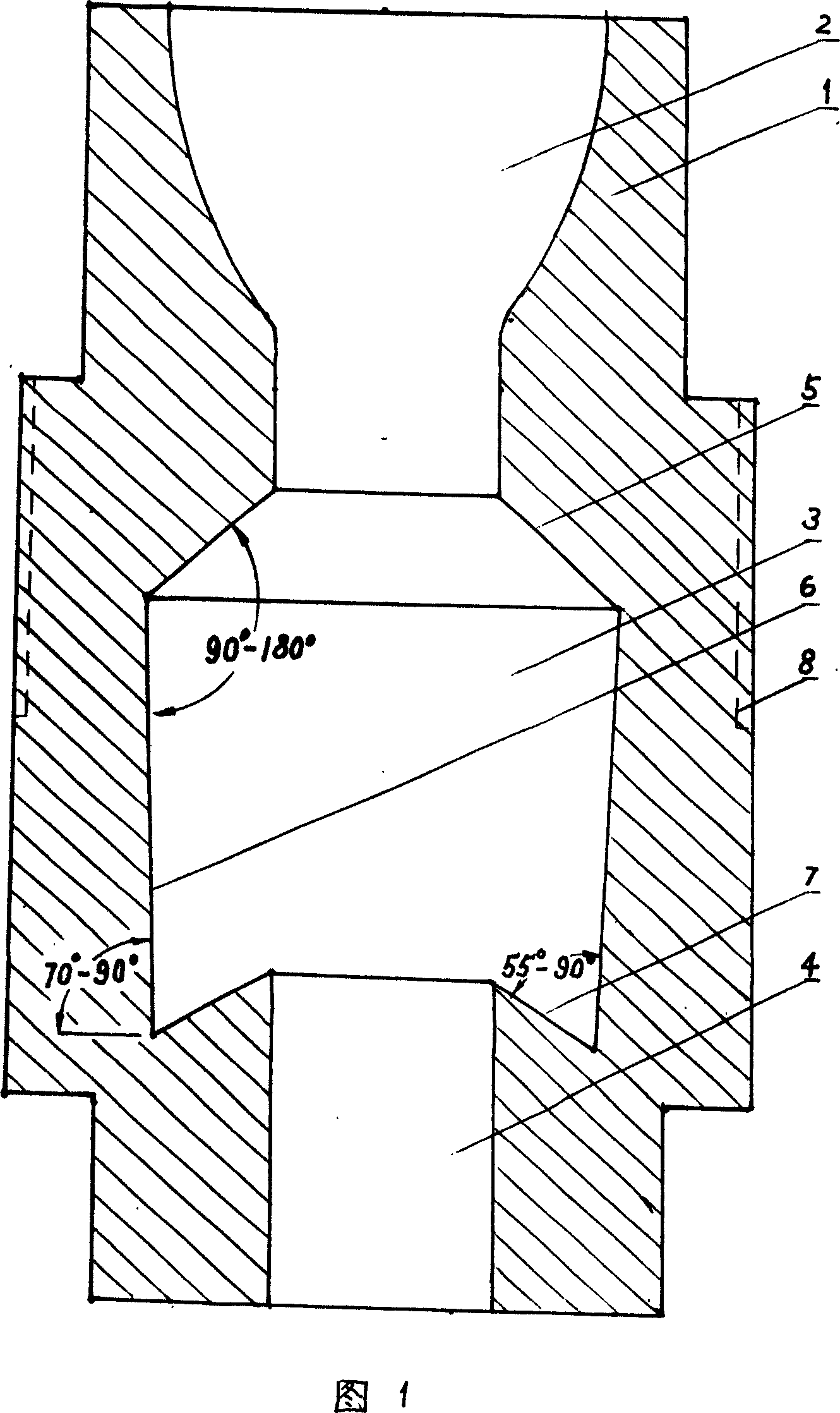
[0011] The specific implementation method is as follows: it includes the housing 1, the inlet hole 2, the resonant cavity 3 and the outlet hole 4; the inlet hole 2 is an arc-shaped surface hole with a large upper part and a smaller lower part, and is located in the upper section of the housing 1; the outlet hole 4 is located in the housing 1 Inner and lower sections; the resonant cavity 3 is located in the middle section of the housing 1, and the resonant cavity 3 is divided into three sections. The peripheral wall of the conical hole forms the upper reflection surface 5; the middle section of the resonant cavity 3 is an inverted conical cavity, and the inner diameter of its upper end is equal to the lower inner diameter of the inner hole of the upper section of the resonant cavity 3, and the peripheral wall forms the middle reflection surface 6, and the middle reflection surface and The angle between the horizontal planes other than the resonant cavity 3 is 85°, the angle betw...


PUM


Abstract

The invention is a self-excited resonant pulse device, belonging to the pulsating sprayer technical field, for providing a self-excited resonant pulse device able to automatically increase in-pipe pressure in transportation. And its technical solution comprises casing, inlet, resonant cavity and outlet, where the inlet is a round hole big up and small down and located in the upper section in the casing; the outlet is located in the lower section in the casing; the resonant cavity is located in the middle section in the casing and the upper section of the resonant cavity is a conical hole with inside diameters small up and big down, and the peripheral wall of the conical hole forms an upper reflecting surface; the middle section of the resonant cavity is a round cavity and the peripheral wall of the middle section of the resonant cavity forms a middle reflecting surface; a cone is formed between the top end surface of the outlet and the bottom end edge of the middle reflecting surface and the surface of the cone forms a lower reflecting surface. And it is mainly applied to liquid or gas pipeline transportation. And it can also be used for well drilling, hydraulic drive and cleaning.

Description

technical field [0001] The invention belongs to the technical field of pulsating injection devices. Background technique [0002] In the long-distance pipeline transportation of oil and natural gas, due to the loss of medium pressure in the pipeline, the pressure will drop a lot when it is transported to the far end. In order to make up for the pressure loss, multiple pressurization stations must be established in the conveying pipeline to pressurize the conveyed medium. The disadvantage of the prior art delivery pipeline is the increase of pressurization equipment, which increases the construction cost and operation cost of the pipeline. Existing technology utility model patent 200320115329. X "a kind of oscillating pulse jet nozzle" is only suitable for drill bits, not for pipeline transportation. Contents of the invention [0003] The technical problem to be solved is to provide a self-excited resonance pulse device that can automatically increase the pressure in the...

Claims


Application Information

Patent Timeline
Patent Type & Authority Applications(China)
IPC IPC(8): F17D1/20F17D3/01
Inventor 宋家英杨进宋家雄
Owner 宋家英
Why Eureka
Try Eureka