Electric power steering device

An electric steering and motor technology, applied in electric steering mechanisms, transmissions, belts/chains/gears, etc., can solve the problems of large nut diameter, increased nut axial length, inability to realize compact design of electric steering devices, etc. Rolling, low vibration effect

Inactive Publication Date: 2007-07-18
NSK LTD
View PDF2 Cites 16 Cited by
  • Summary
  • Abstract
  • Description
  • Claims
  • Application Information

AI Technical Summary

Problems solved by technology

However, this entails a large size design of the device
On the other hand, when a tube or part usually used for ball circulation purpose is used, power transmission can be achieved through the nut end surface, but there is a problem that the outer diameter of the nut becomes large
[0008] Therefore, considering that the gear of the nut is arranged to be offset outside the rolling passage in the axial direction, torque transmitted from the motor is input to one end of the nut, and therefore, the nut is easily twisted, making it impossible to achieve smooth power transmission
In addition, in the case of transmitting a large torque, the tooth width of the gear must be increased in order to reduce the contact pressure of the tooth surface, but this increases the axial length of the nut, thereby causing the problem that the motor cannot be realized. Compact design of the steering unit

Method used


Image

  • Electric power steering device
  • Electric power steering device
  • Electric power steering device

Examples


Embodiment Construction

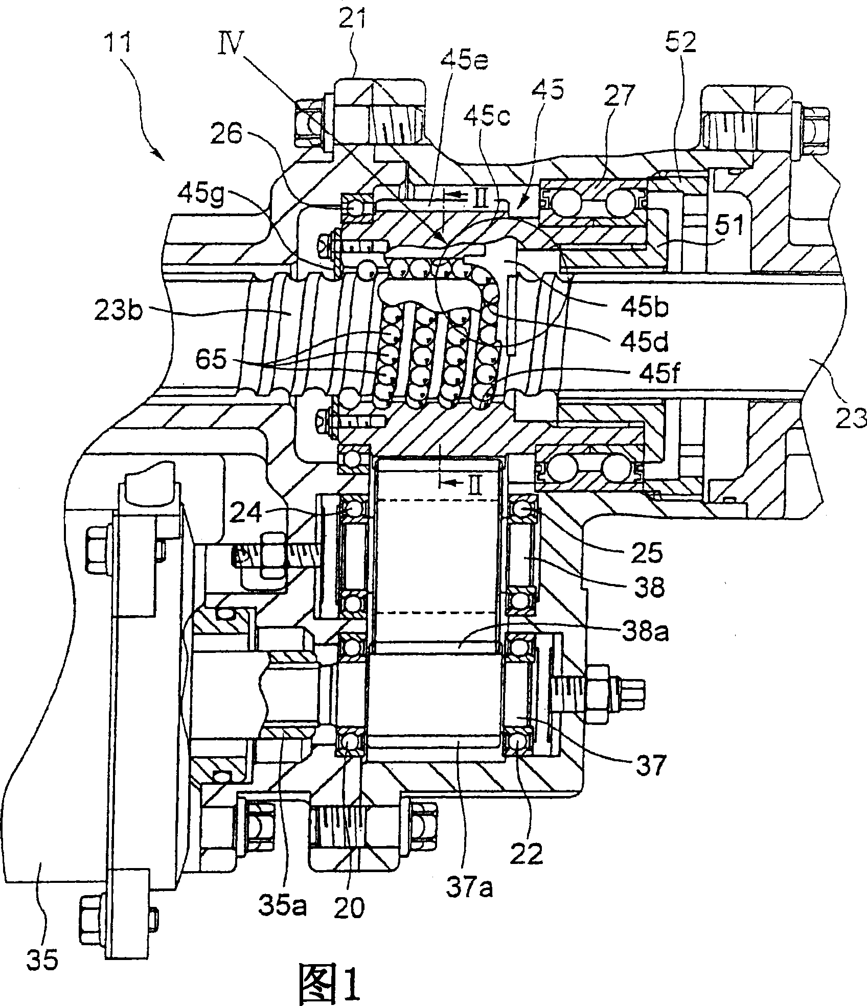
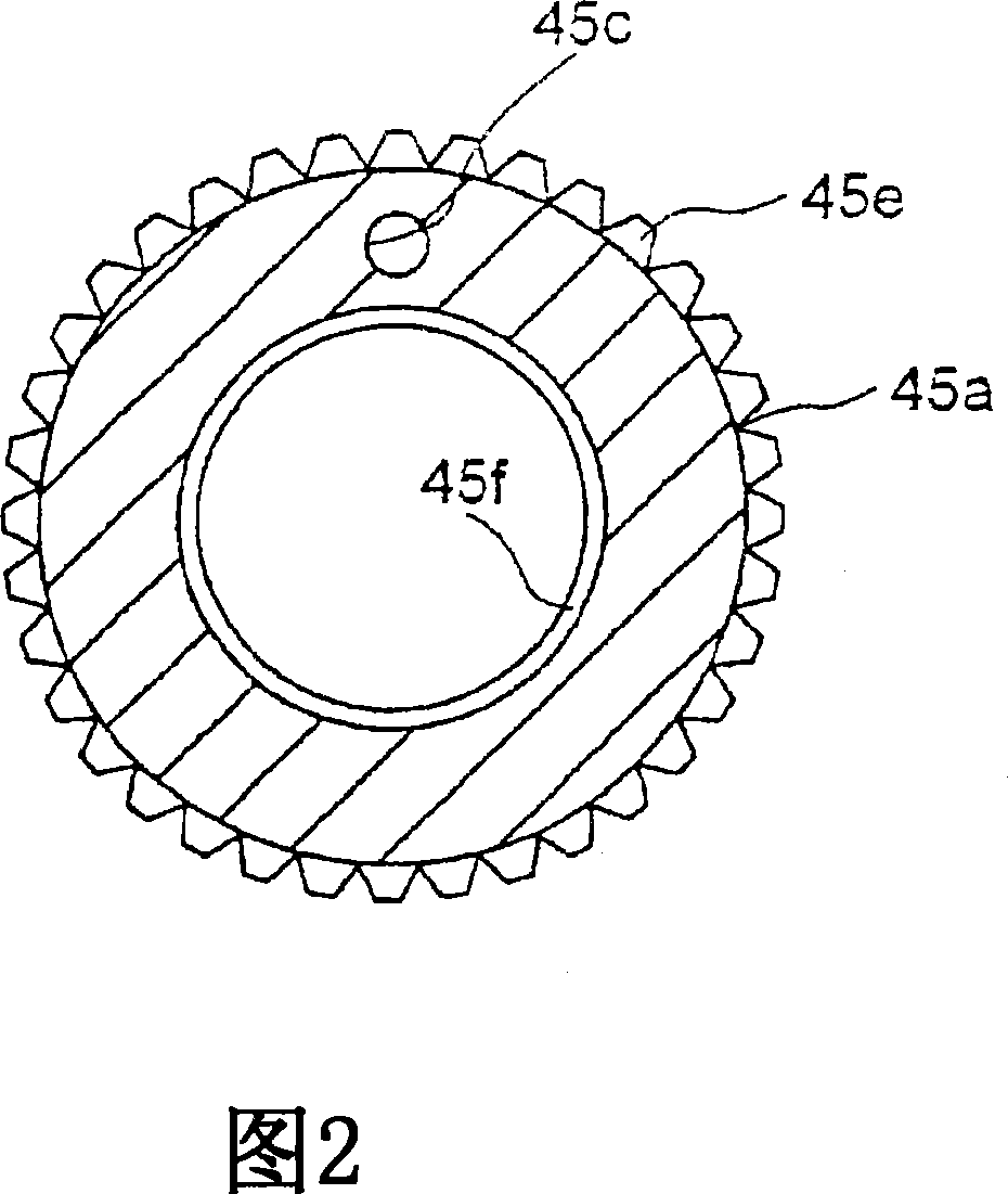
[0153] Embodiments of the present invention will now be described with reference to the accompanying drawings. FIG. 1 is a sectional view of an essential part of an electric power steering apparatus of a first embodiment. Figure 2 is a view taken along the line II-II of the nut of Figure 1, viewed in the direction of the arrow, but with the threaded shaft and balls omitted. In FIG. 1 , an electric power steering device 11 includes a housing 21 fixed to an unshown vehicle body. The rack shaft 23 extends through the housing 21 in the horizontal direction, and is supported so as to move in the axial direction. Although not shown, a pinion gear is formed at the lower end of the input shaft connected to the steering wheel, and meshes with the rack teeth of the rack shaft 23, and the rack shaft 23 moves left and right in the drawing by the rotation of the input shaft. . The opposite end of the rack shaft 23 is connected to a connecting rod (not shown) of the steering mechanism. ...


PUM


Abstract

A deflector (45b) of a nut (45) scoops up balls (65) from rolling raceways (23b, 45f) to a tangential direction of the rolling raceways, in the direction of a lead angle. As a result, the balls (65) are scooped up to a circulation path (45c) with their direction of rolling unchanged, so that smooth rolling can be achieved, and operation noise and vibration can be suppressed to low levels.

Description

technical field [0001] The invention relates to an electric steering device provided with a ball screw mechanism. Background technique [0002] There is known an electric steering apparatus in which an electric motor is driven according to steering torque, and the rotational force of this electric motor is transmitted by transmitting the rotational force to a rack shaft in order to assist the steering operation. Here, in some cases, a ball screw mechanism is used in order to convert the rotational force of the motor into the thrust force of the rack shaft (see JP-B-6-504 publication). [0003] Incidentally, in the electric power steering device described in the JP-B-6-504 publication, a gear is integrally formed on the outer periphery of a nut of the ball screw mechanism, and the power of the electric motor is transmitted to the nut through this gear. Therefore, in order to obtain high-speed rotation of the nut, it is desirable to suppress its inertia. Also, it is desirabl...

Claims


Application Information

Patent Timeline
Patent Type & Authority Applications(China)
IPC IPC(8): B62D5/04F16H25/22
Inventor 冈田淳立胁修斋藤修
Owner NSK LTD
Why Eureka
Try Eureka