Apparatus for transferring of glass panel

A flat glass, conveying device technology

Inactive Publication Date: 2007-07-25
TAE SUNG ENG
View PDF0 Cites 12 Cited by
  • Summary
  • Abstract
  • Description
  • Claims
  • Application Information

AI Technical Summary

Problems solved by technology

[0003] However, there is a problem in such a conventional plate glass conveying device, that is, when damage such as a crack occurs in the conveyed plate glass, the defective plate glass is not detached to the outside in the direction of both sides of the conveying line, but After continuing to be conveyed in the direction of travel, it is separated from the discharge part at the end to the outside, so it takes a lot of time to remove the defective flat glass, and when removing the defective flat glass, the operation of the entire conveying line must be stopped, which greatly reduces the work efficiency
[0004] In addition, the conventional plate glass conveying device also has the following problems, that is, in order to support the conveyed plate glass with air, a large fan of the FFU system is used, which requires another chamber for installing a large fan, etc., making the entire structure Become extremely complex and large, and make a lot of noise due to the operation of large fans
[0005] In addition, the conventional flat glass conveying device also has the problem that, on the working line, the conveying device manufactured in an independent unit structure according to the conveying distance is continuously arranged to form a conveying line. Therefore, each unit requires Workbench, which not only requires a lot of production costs, but also when moving the device, the number of handling is large and the handling is difficult
[0006] In particular, the conventional sheet glass conveying device has the following extremely serious problem, that is, when the sheet glass is conveyed, if the air discharged from the air flotation device to the upper part is concentrated in the central part of the lower part of the sheet glass, the The air is trapped by the air that is continuously discharged from the surrounding area. Therefore, the expansion phenomenon of the flat glass occurs due to the concentration of the air in the center, and it will cause defects even during the transportation process.

Method used


Image

  • Apparatus for transferring of glass panel
  • Apparatus for transferring of glass panel
  • Apparatus for transferring of glass panel

Examples


Embodiment Construction

[0035] Hereinafter, preferred embodiments of the present invention will be described in detail based on the drawings.

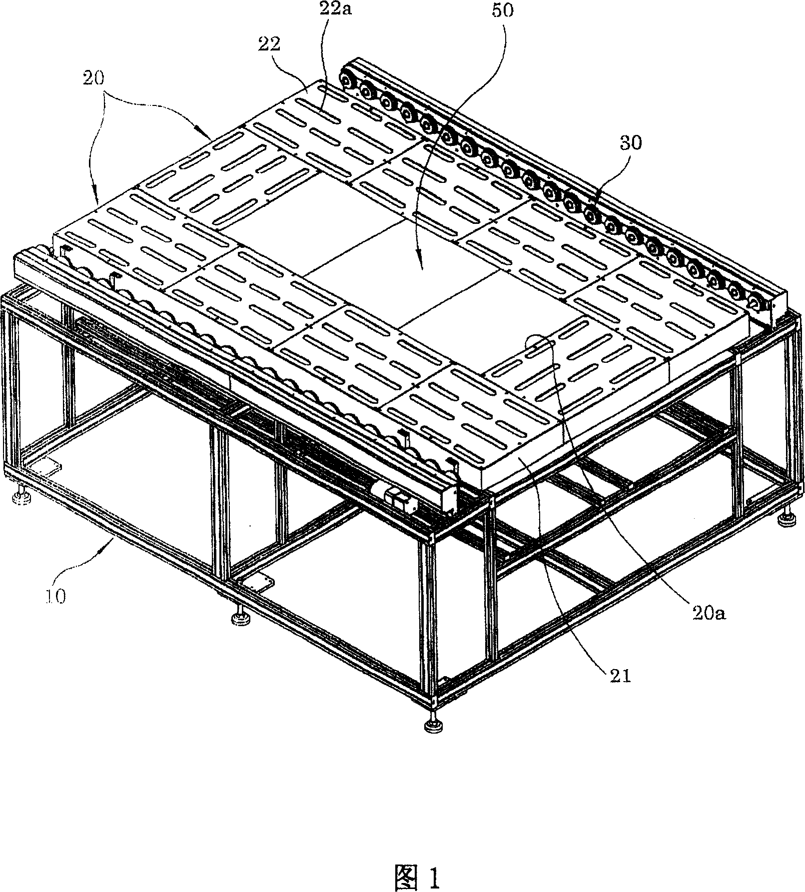
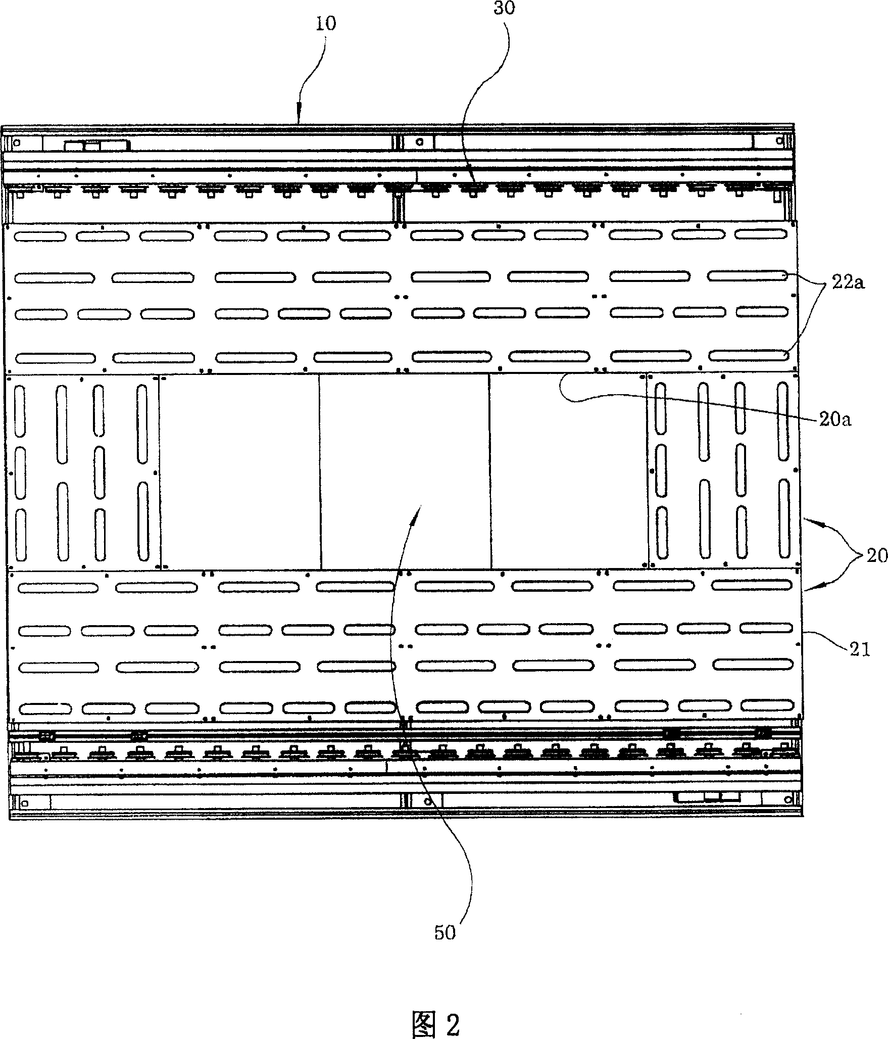
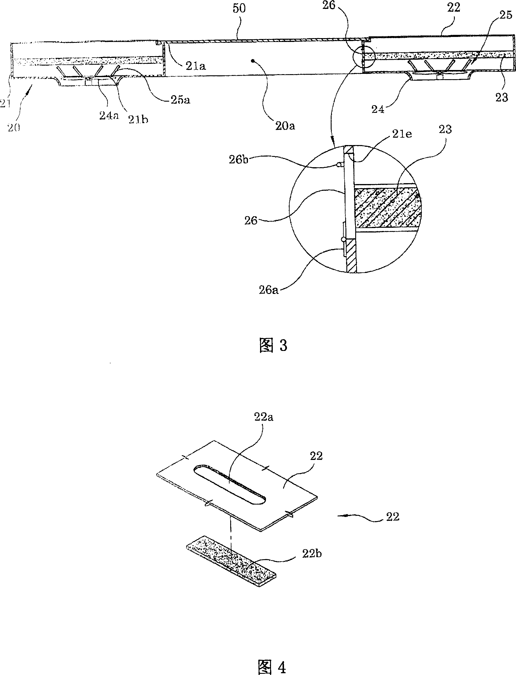
[0036] Fig. 1 is a perspective view of a flat glass conveying device according to a first embodiment of the present invention, Fig. 2 is a top view of a flat glass conveying device according to a first embodiment of the present invention, and Fig. 3 shows a flat glass according to a first embodiment of the present invention Fig. 4 is an enlarged exploded perspective view showing partial highlights of the top plate of the air flotation device in the flat glass conveying device according to the first embodiment of the present invention.

[0037] The plate glass conveying device according to the first embodiment of the present invention includes: an air flotation device 20, which is arranged on the upper part of the workbench 10, and discharges the air supporting the plate glass 40; a conveyor 30, which is arranged on the above air flotation device 20 The two si...


PUM


Abstract

The invention provides a flat glass conveying device which can quickly deal with unqualified flat glass and makes the integer compact by miniaturizing the structure of an air flotation device and reduces the noise to facilitate after-management. The flat glass conveying device includes: an air flotation device 20 disposed at the upper part of a worktable 10 and discharging air upwards from each vent 22a formed on the upper surface; conveyers 30 disposed at the both sides, in width direction, of the air flotation device 20 and employing the discharged air to keep the flotation-support state to convey the flat glass 40 moving over the air flotation device 20, wherein, in the air flotation device 20, the central part, beside periphery, is formed by through holes 20a which vertically run-through the air flotation device 20, and on which shield plate 50 is disposed.

Description

technical field [0001] The present invention relates to a conveying device for flat glass, and in particular relates to a process in which flat glass is conveyed in a state of balanced support by using the air discharged from the air flotation device, so that no expansion phenomenon occurs, and the air flotation on the production line can be carried out conveniently and quickly Flat glass conveying device for connection work of the device. Background technique [0002] Generally, a sheet glass conveying device that conveys sheet glass in a state supported by exhaust gas has an air flotation device on the upper part of the table and conveyors installed on both sides thereof, and such a conveying device operates as follows: Most of the flat glass moving on the upper part of the air flotation device, except for the ends on both sides of the conveyor, is maintained in a balanced state by the air discharged from the air flotation device to the upper part, along the specified work...

Claims


Application Information

Patent Timeline
Patent Type & Authority Applications(China)
IPC IPC(8): B65G49/06
CPCA47L11/283A47L11/34A47L11/4038A47L11/4069A47L11/4083A47L11/4086
Inventor 郑孝才
Owner TAE SUNG ENG
Why Eureka
Try Eureka